Well I have said this over and over in this thread, if you aren't confident you can handle the soldering part of the mod then don't even attempt it.
With me for example, all I needed was the diagram and the replacement cap values and I was off to the races. If you don't feel like you are somewhere in that ballpark, especially the soldering part, don't attempt it.


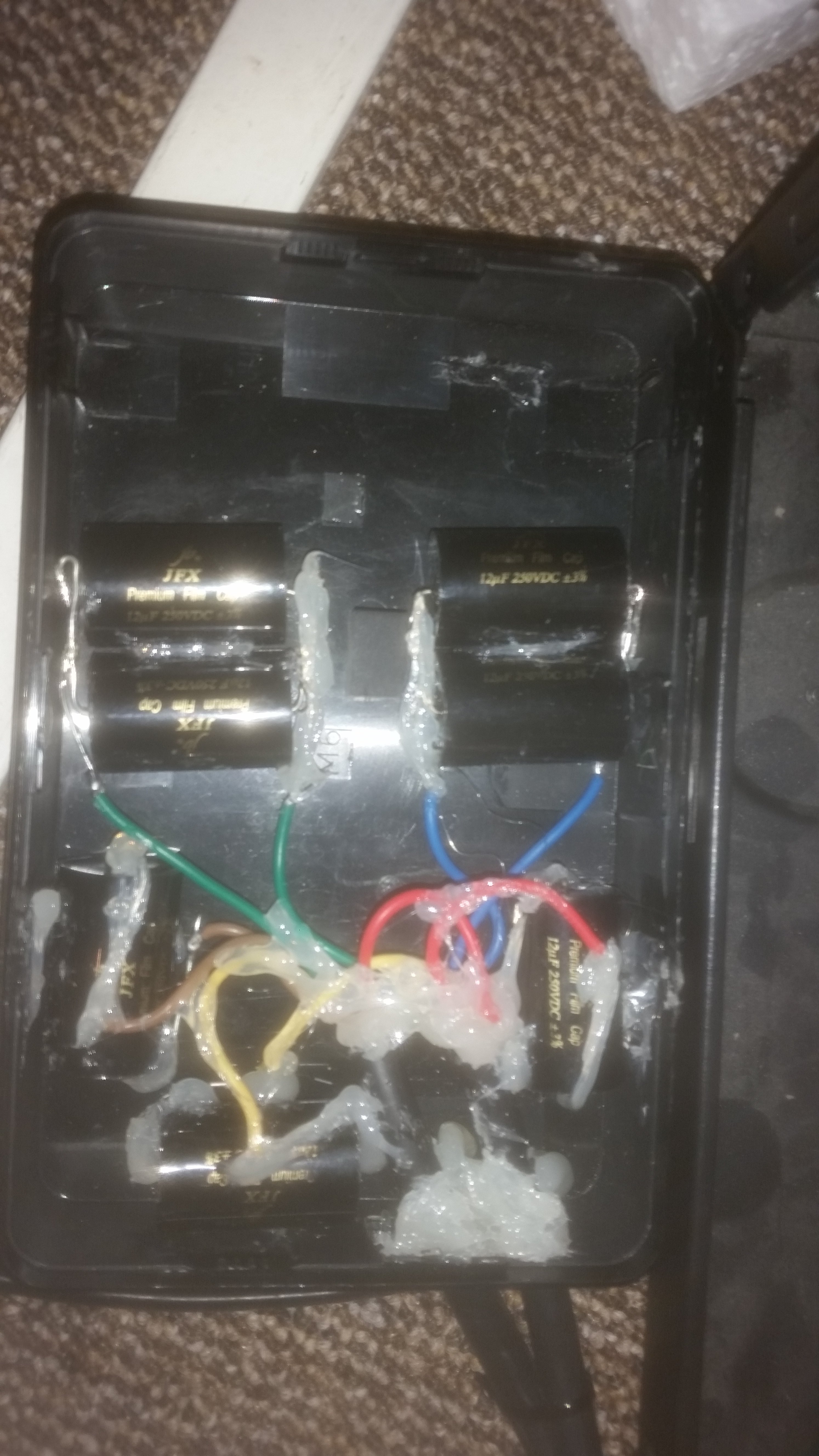
![20180317_143924[6054].jpg](https://cdn.head-fi.org/a/10085164.jpg)