First Build - CMoy Help (800 KB pics)
Dec 29, 2004 at 4:27 PM Post #31 of 53
Ah, Memories.
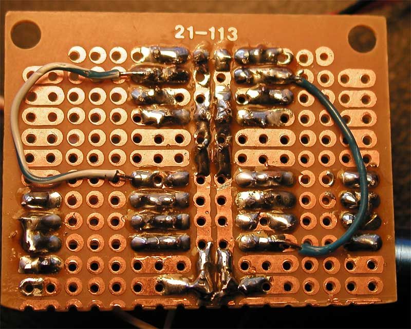
My first cmoy, which I built not long ago, looked like this. The soldering job was so sloppy and I had so many cold joints that I had to scrap the project and start over with a new board. It took me about 3 tries to make a good amp. I had the exact same problem as you, with uneven voltages between V+ and V-.

What I do now to make sure everything will work is test all my joints with a DMM right after they are done. If you read more than .10 ohms on your meter, its probably cold and needs some work. I also check between pads that shouldnt be connected for solder bridges and clean them up with some desoldering braid, which is really great stuff. Clean up all solder bridges between all pads. There should only be a solder connection between holes on like pads so the jumpers can work.

Looks like youre burning up the board a bit too, and I *think* you may have the switch wired wrongly.

I recomend scrapping the project and starting over on a fresh board and if you can, use new caps. The project isnt a failure if you learn from the experience. If you test everything all the time, take care and make a point to move slowly, I would say the chances of making a working amp approach 100 percent
600smile.gif


Hope this helps
 
Dec 29, 2004 at 6:52 PM Post #32 of 53
I think I read somewhere about faults that the circuit protects from.

I found that for the first like 0.1 second of operation (switched turned on) I can hear music and sound, but after that, nothing. Am I just better off starting over?
 
Dec 31, 2004 at 12:23 AM Post #33 of 53
No, don't start over. At least give it a chance to troubleshoot what you got, that way you will learn a lot more about building electronics.

The soldering in general looks acceptable, so if you got a bad joint it is probably only a single joint.

Since it work for a short while I would guess that you got a problem with the power supply. When the caps charges up something gets shifted so the virtual ground goes near one rail.
I suggest that you replace the phones with resistors. Preferably quite large to start off with, like 1K or 470ohm.
Measure the rail voltages compared to virtual ground and see if they are still bad. If they are fine switch to a lower value resistor and try again.
Also put your finger on the op-amp (and other components) to feel if they get hot. If something gets hot you have a problem, and that component is probably in a short circuit somehow.
 
Dec 31, 2004 at 3:28 AM Post #34 of 53
I think that might be what is happening..as I said before, when I turn it on positive side reads 15 V and the negative side reads 3 V. It should match I think...

And nothing is getting warm either! What else should I be looking at? I switched to testing with some other headphones, but shouldn't all basic headphones work?
 
Dec 31, 2004 at 6:02 AM Post #35 of 53
ok, u've got a problem first in ur power supply unit, [top of the board] check to see if the resistors are 4.7kohm and that caps are right polarity, and also check to see if theres any solder bridges etc, also make sure u solder all the legs in

cc541fe1.jpg


this might help
 
Dec 31, 2004 at 7:06 AM Post #36 of 53
I'm using Grados and I think that might be part of the problem. I guess they require very high amperage or something because they're very low impedence. Could that be the case?
 
Dec 31, 2004 at 9:37 AM Post #37 of 53
Quote:

Originally Posted by deadlierchair
I'm using Grados and I think that might be part of the problem. I guess they require very high amperage or something because they're very low impedence. Could that be the case?


Well, that is what I suggested in my previous post...

Try adding the r5's, or even better, try the troubleshooting silvervarg suggests. You have received some suggestions on how to fix this. Try them first, and ask again if you can't get them to work.

Knut
 
Jan 4, 2005 at 5:27 AM Post #38 of 53
Quote:

Originally Posted by enemigo
Well, that is what I suggested in my previous post...

Try adding the r5's, or even better, try the troubleshooting silvervarg suggests. You have received some suggestions on how to fix this. Try them first, and ask again if you can't get them to work.

Knut


I tried using R5's that were the 100 K resistors with my iPod phones, Grado's, and Shure E2C's. I still had the same problems pretty much. Should I try the 47 K resistors also?

I am ready and willing to try what silvervarg is suggesting, however I am not sure how to implement it. I have some 1 K resistors around. How should I hook those up as a fake load ouput?

EDIT: And should I still worry that I'm getting 15 V + and 3 V -, without any input or output at all?
 
Jan 4, 2005 at 2:55 PM Post #39 of 53
Quote:

Originally Posted by deadlierchair
I tried using R5's that were the 100 K resistors with my iPod phones, Grado's, and Shure E2C's. I still had the same problems pretty much. Should I try the 47 K resistors also?


That should be 100 ohms or 47 ohms. K ohms is WAY too much.

Quote:

Originally Posted by deadlierchair
EDIT: And should I still worry that I'm getting 15 V + and 3 V -, without any input or output at all?


Yes, that is not good. The amp would work, but would clip on the negative swing way sooner than on the positive swing.

Did you try pulling the opamp and ohming out all the pins to ground, to each other, etc. as I suggested previously? This has helped me find alot of problems in CMoys. If you aren't seeing what you expect to see in pin to ground (virtual ground), then figure out why. For example, pins 3 and 5 are the inputs and have R2 (I thing) of 100K to ground. If you aren't seeing 100K, then something is wrong (well, as long as you have input caps at least). And so on.
 
Jan 4, 2005 at 5:28 PM Post #40 of 53
I had a similar problem on my cmoy, and it turned out to be weak batteries. Can you try new ones? Chances are, this isn't it, but its easy to try.
 
Jan 4, 2005 at 11:05 PM Post #41 of 53
Quote:

Originally Posted by Pars
That should be 100 ohms or 47 ohms. K ohms is WAY too much.


That's got to be my problem! As soon as I get home I'll throw a resistor like that on it and see what happens.

Quote:

Originally Posted by Pars
Did you try pulling the opamp and ohming out all the pins to ground, to each other, etc. as I suggested previously?


I tried a couple steps ago and I had results that were just fine. When I get home I will run those same tests again. Thanks!
 
Jan 4, 2005 at 11:41 PM Post #42 of 53
Having just completed my first successful CMOY yesterday after about five build attempts, and considering that I had the exact problems you're having now...

Yeah, make sure soldering is all okay. What I do is, after I've done the all the soldering, I take the pointy tool that came with my radio shack soldering kit - just use some sort of tool that comes to a sharp point, like a really small nail set or even a metal toothpick - and scrape in between all the rows on the board. This always solved my soldering problems, because I could FEEL where the miniscule bridges were and either scrap them out or melt them out.

Also, your input and output ground wires are grounded on the chip in a different location than I use. Try attaching grounds to one of the two center strips of the board.
 
Jan 5, 2005 at 3:27 AM Post #43 of 53
I have added in two R5 resistors. Both are 47.5 Ohm. However, my problem persists. With everything connected, when I switch power on I hear sound for about 0.1 seconds and then it shuts off.

Something I have now noted is that my voltage readings change once I plug in my Grado headphones (impedence 32). The voltage goes from 14.92 to 16.22 from the Positive side (before it goes through and resistors or caps etc and also on the + input on the opamp). The negative voltage goes down as to total about 18 ( 2 X 9v batteries).

My input and output ground wires are fine because they are both connected to my ground loop. I also just checked around for any more bridges and found none.

Do I just have a bad amp? Did I kill it on accident?

EDIT: I have been trying to test my tube caps with my multimeter's capacitance test and am not getting any clear results. Maybe that's a problem? Or probably with just my meter...

Also, when testing, I switched the power supply leads once on accident and the amp got pretty hot, but that was for like 2 seconds. Could that have killed it or the caps?
 
Jan 5, 2005 at 2:49 PM Post #44 of 53
Quote:

Originally Posted by deadlierchair
I have added in two R5 resistors. Both are 47.5 Ohm. However, my problem persists. With everything connected, when I switch power on I hear sound for about 0.1 seconds and then it shuts off.

Something I have now noted is that my voltage readings change once I plug in my Grado headphones (impedence 32). The voltage goes from 14.92 to 16.22 from the Positive side (before it goes through and resistors or caps etc and also on the + input on the opamp). The negative voltage goes down as to total about 18 ( 2 X 9v batteries).

My input and output ground wires are fine because they are both connected to my ground loop. I also just checked around for any more bridges and found none.

Do I just have a bad amp? Did I kill it on accident?

EDIT: I have been trying to test my tube caps with my multimeter's capacitance test and am not getting any clear results. Maybe that's a problem? Or probably with just my meter...

Also, when testing, I switched the power supply leads once on accident and the amp got pretty hot, but that was for like 2 seconds. Could that have killed it or the caps?


Reversing the power, even for 2 seconds, could bugger the opamp, and possibly the PS caps (electrolytic). This is why many amps use a crowbar diode (see Tangent's MINT for example).

The first two CMoys that I built, I accidentally put 470 ohm resistors in for the R5s and had loud, really distorted sound until I discovered the problem (which would have been shown by ohming out the pins on the jack). Also, it isn't clear in your photos how the jacks are wired... from the photos it looks like the white and black wires are connected to the same pin on the jack? This would not be correct. These are stereo jacks? If so, there should be at least 3 connections (more if it is a switching jack), one for L, R and ground. Verify which is which by inserting a plug into the jack. Tip is left, ring is right and the sleeve is ground.
 
Jan 6, 2005 at 12:24 AM Post #45 of 53
Quote:

Originally Posted by Pars
Reversing the power, even for 2 seconds, could bugger the opamp, and possibly the PS caps (electrolytic). This is why many amps use a crowbar diode (see Tangent's MINT for example).


All of my input and output connections are fine, the pictures make it look differently but they are wired correctly. I have tested multiple times and wired it incorrectly at first, but now they are fine.

I was afraid that it might be dead...well, it happens. I'll order up a new one if replacing the two power supply caps doesn't help. Thanks for your continuing help everyone!
 

Users who are viewing this thread

Back
Top