eXStatA Build Thread II

Feb 13, 2011 at 8:42 AM Post #481 of 588
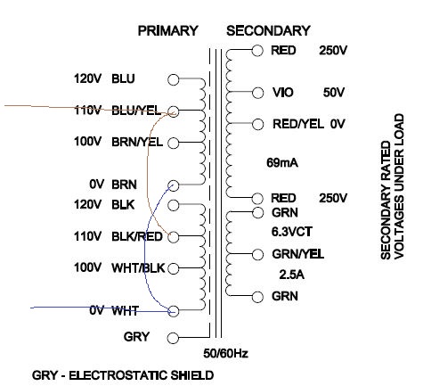
I messed up my PSU, so I tried build a salas SSHV instead. It came alive (after some trouble with dead mosfets) last night :D

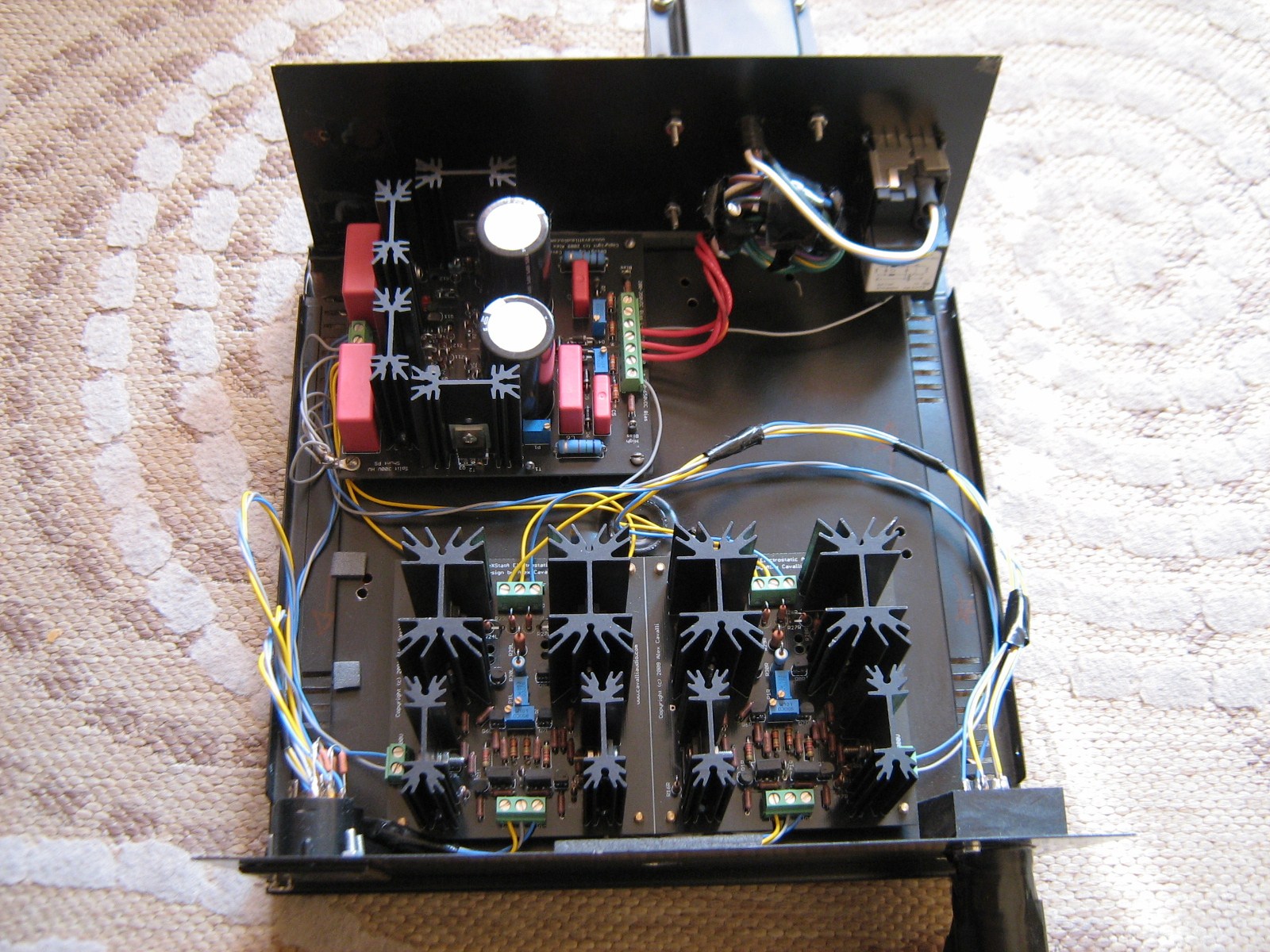
Then connected the SS-amp modules.
One of them works!, and i could adjust difference in output Voltage to 0V with P2

The other one dont :mad:
Anyone has some good input?
I tried measured the voltage (with reference to ground) around the circuit:

voltage on good amp in ()
out- +285V (11)
out- -295V (11)
P2/R36 -18,9V (-1,52 on good amp)
P2/R35 -19,3V (-1,53 on good amp)
R36/Q2 -18,8V (-1,57 on good amp)
R35/Q1 -19,4V (-1,56 on good amp)
R26/R27 297 (201)
R27/R28 291 (106)
R23/R24 100 (202)
R24/R25 -91 (106)
R33/R34 130 (5,4)
R32/R31 -156 (5,0)
Q4/R6 -300 (-243)
Q3/R5 -300 (-243)
R11/R12 -160 (-160)
R6/Q7 -300 (-300)
R5/Q6 -300 (-300)

Then my child woke up from sleep ...
I might try to check the transistors tonight ...
[[EDIT: 14/2]]
All KSC5027 (replaced 5042) measured ok on both amps (HFE around 25 in circuit)
both 1156 is hard to measure in circuit (HFE around 2 in circuit ... :confused_face: ) But the same on both amps.

Q1 and Q2 (sj74 bought on ebay, matched quad with Idss around 15,9)
- both has a drain-to-source resistance about 75ohm on good amp
- on bad amp Q2 has 75 ohm as well, but Q1 is 88 ohm.
Is that enough to change the pair? i'd suspect a bigger deviance, if the fet was blown....

the BC550's is hard (impossible) to measure in circuit ...

Anyone got some tips??
]]


Peter
 
Feb 15, 2011 at 7:40 AM Post #483 of 588


Quote:
Yes, agreed. This is one of the reasons that the KSC5042 was chosen in the first place. As the project owner, I don't expect that there will be any more board runs or group buys. This particular design has served its original purpose.
 
A good solution for anyone who can't find the KSC5042 is to use the Sanyo device.


[size=10pt]I have found a Sanyo 2SC 3676 device is TO 220 packaging, has Cob 5 pF, Hfe 30 and Vceo 900V think it is a real good replacement part - what do you think? [/size]
[size=10pt]Hope it is still in production, can somebody advice a source for Europe especially Germany [/size]
[size=10pt]THX[/size]
[size=10pt]pertube[/size]
 
Feb 15, 2011 at 11:08 PM Post #484 of 588
Well, I can speak to that. Having had (past tense) a bunch of 2sc3676, all my builds have them, and they work very well. I had mine from having used them in the Blue Hawaii, and needed a bunch...   :-)
 
No sourcing ideas, as mine were purchased years ago.
 
Feb 16, 2011 at 12:40 PM Post #486 of 588
This design doesn't seem particularly susceptible to induced power supply hum, but you've got your power transformer pretty tight against your amp boards. If the louder left side is the board that is closest to the transformer it might be an indication some interaction is going on.  If there is interaction, extra space or perhaps physical reorientation of the transformer would be the answer. Or if you want to keep your nice tight build , try an R core or toroid.
 
Feb 17, 2011 at 9:04 AM Post #488 of 588
I just took out the power transformer and put it further away from the left channel board and the hum did really go away.  I tried to rearrange the transformer, but, unfortunately my enclosure was just too small.  I guess I just have to live with this little hum.  :(
 
Wachara C.
 
Feb 17, 2011 at 11:02 AM Post #490 of 588
Quote:
I just took out the power transformer and put it further away from the left channel board and the hum did really go away.  I tried to rearrange the transformer, but, unfortunately my enclosure was just too small.  I guess I just have to live with this little hum.  :(
 
Wachara C.


I've come around to making my builds 2-case ones at this point (e.g. wallwart or DIY power brick in small headamp cases).  IIRC the only ones that are really happy w/transformers in their cases are using (expensive) potted toroids, or others as Frank suggested.  Might not be feasible/desirable for this project or this build but I've taken to putting the transformers in their own cheap case (fused, etc) that can sit on the floor w/multiple-conductor output wire + DIN connectors & such depending on load.  This is a HV project, so it'd be trickier & more expensive I guess.
 
From what I've read & from playing around with metal shielding plates is that they may help but electromagnetic fields are stubborn.  I've had some success rotating transformers but distance (e.g. 6"+) is your friend.
 
Feb 17, 2011 at 12:14 PM Post #491 of 588
iron (low carbon steel) is a cheap magnetic conductor - but there is no "magnetic gnd"  you have to think in terms of spatially "shorting out" the field
 
 
you also have to avoid creating a hazard with electrical shorting to the added metal or causing over heating with a closed box - perforated heavy gage low carbon steel was used in the classic Lambda linear supplies
 
 
sometimes twisting (the right pairs), moving signal wiring relative to power can help - as does twisting power wiring to minimize magnetic field radiating loop area
 
Feb 17, 2011 at 2:16 PM Post #492 of 588
Why not just modify it to use 2 cases?  You can connect the chassis/earth with an earth wire strapping the 2 chassis together.  In that way, you've more or less built a faraday cage for the transformer.  Use the appropriate connectors for the power feeding into the amp section.  It'll be more expensive, but I wouldn't live with a hum like that.  You can keep the PSU in the amp case, but move the transformer out.
 
A piece of iron shielding the transformer may help, but it looks too tight in your chassis to really attach it anywhere.  You can try bisecting your case between the power and amp boards, but try not to short anything out.
 
Use an isolation transformer with a fuse, and fuse your circuit, just in case things do short out.
 
Feb 17, 2011 at 5:30 PM Post #493 of 588
 
chinsettawong,
 
now I see the pics, - reroute wiring! - "best" would be put inputs on front panel (output too usually but at esl V levels, balanced output it won't make any hum difference)
 
looks you can't get to far from the xmfr but get signal wires as far away as possible - more uniform mag field at a distance mean twisted pairs (even coax) work better at rejecting hum
 
you also want to stay away from ps rectifier current loops which give "buzz"  - this probably means running input wire signal/gnd pairs along top edge of case on the side away from the xfmr
 
heater wiring doesn't look like tightly twisted pairs - these carry the highest line frequency current in the box and should be twisted in +/- pairs (for each heater) to cut radiating loop area to the min
 
pwr entry wiring to any sw, fuse, iec to xfmr should all be twisted pairs of line/neutral or hot/switched -  any current loop should be made small by twisting the wires and their "returns" and they should be moved as far from the signal wires as possible
 
 
but the biggest improvement should be expected from properly using the balanced input on each amp board
 
it looks like you're not taking advantage of the amp board's differential inputs, the minus input shouldn't be jumpered to board gnd - it should be the signal gnd from the RCA input - the (tightly twisted pair, 3-wire flat cable gnd-sig-gnd, star quad or gnd shield of RCA/coax) signal gnd wires for each channel should be carried from the input connector to the pot and from the pot gnd to each amp minus input individually - as closely following each channel's signal wire as possible - it looks like you already have isolated the RCA from the case
 
with RCA near the power end of the box you really want spatially "balanced" signal gnd - don't leave a asymmetric mag field sampling loop where the signal enters the case - at least bend ring washer tab closer to the RCA central axis - better still to use a couple of identical washers evenly spaced and tease out pigtails 180 degrees apart on a nice RCA coax braid (or again 3 wires in flat cable evenly spaced gnd-sig-gnd gives a type of mag field rejecting cable, star quad is great too)
 
somewhere each signal gnd will need to connect separately to board/chassis/safety gnd with 10-100 Ohm resistors - to limit the input common mode range - but you don't want any differences between the signal and signal gnd wiring from RCA connector to the +/- input of the amp board to take advantage of the balanced input's common mode rejection ability
 
Feb 21, 2011 at 12:54 PM Post #495 of 588
hey Peter,
 
Any progress?


Found the problem. (With some help from Alex .. thanks!)

I changed the 2 FETs (2sj74), and it works now :D

I suspect, it was Q1, that was too "open", and got all the current. I measured Idss to around 30 (!!) and a bit fluctuating - it was suppused to be matched with the other one at 15,9mA

Now i "just" need to wire, and assemble the cabinet ... ;)

peter


Users who are viewing this thread

Back
Top