eXStatA Build Thread II
Jul 15, 2010 at 5:55 PM Thread Starter Post #1 of 588

runeight

Member of the Trade: Cavalli Audio
Joined
Oct 10, 2002
Posts
2,941
Likes
1,422
Starting this thread for all of the new builders who are getting eXStatA boards through the latest group buy.
 
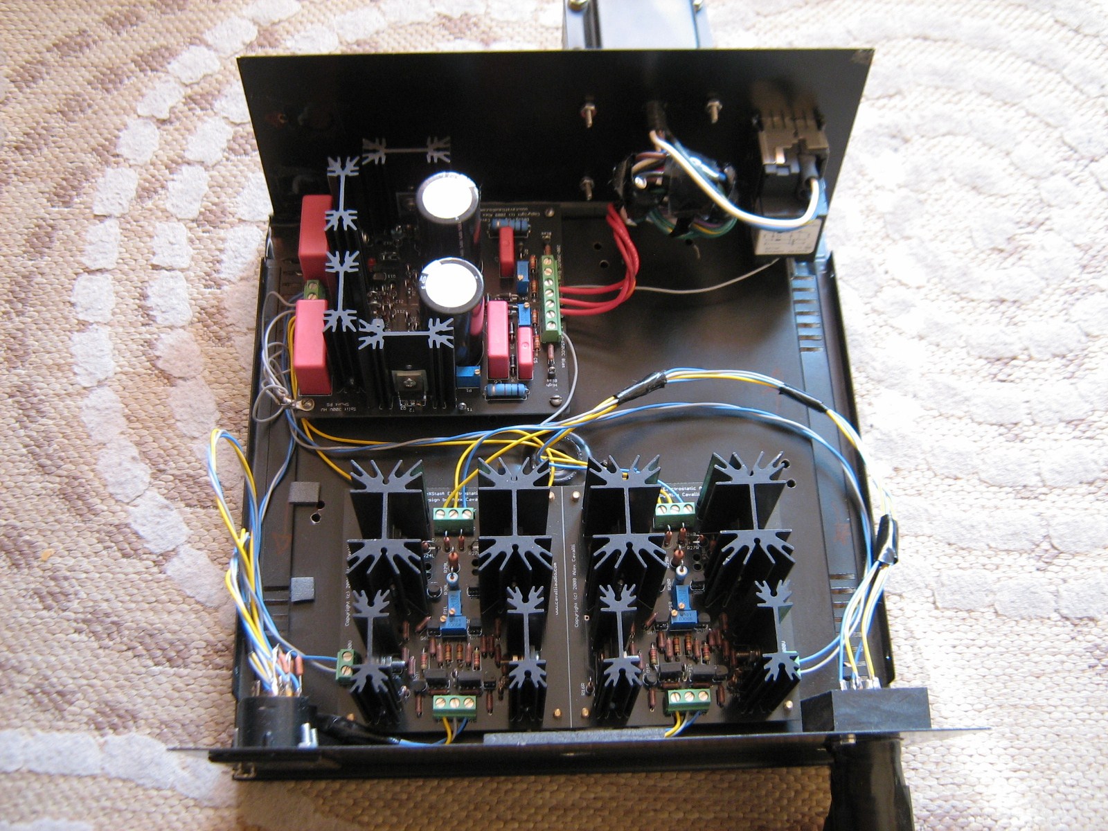
One piece of technical info for you new builders. On the website there is a fix to kill oscillation in the first beta run. This fix entails wiring two of the heatsinks to ground. A diagram is provided on the website.
 
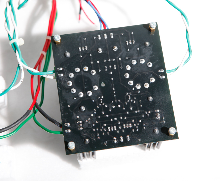
The new boards, however, already have this grounding built into the traces. All you have to do is to be sure to solder the two CCS heatsinks on each board to their pads. I'll try to add this info to the webiste.
 
This applies only to the SS board. I recall that the hybrid board did not need this fix. But I may remember wrong. If so, then the fix is still to wire the heatsink pins to the ground point at the input terminal block.
 
In addition, all of the heatsinks now have metalized pads so that you can solder them in place.
 
In all other respects the new boards are the same as the original betas, all of which worked when built correctly.
L3000.gif

 
Jul 16, 2010 at 3:32 PM Post #3 of 588
Alex, The hybrid boards need the heatsinks grounded, too, or at least mine did, to keep the amp from oscillating.
ksc75smile.gif

 
Jul 16, 2010 at 5:49 PM Post #4 of 588
Shoot. I couldn't remember.
confused.gif

 
Well, sorry folks, those of you who got the hybrid boards, you'll probably have to wire the CCS heatsinks to ground. Several previous builders can help with this.
 
Jul 17, 2010 at 11:03 AM Post #5 of 588
Hello Gents.  I have populated everything on my PS board except for the C1 – C2 caps and the heatsink/transistor assemblies.  I need to ask a couple of questions about them before proceeding:
 
(1)  Why are there two sets of mounting holes for the C1 and C2 caps?  I see on the underside of the board that the two negative holes for C1 and the two positive holes for C2 do not seem to lead to anywhere.  Anyway, does it matter in which sets of holes I mount these guys?
 
(2)  I have collected most of the photos posted on the threads to help me with this build and see (I think) that the heatsinks on some of the PS boards have been shimmed before mounting:  i.e., there is a space between the bottom of the heatsinks and the top of the board.  Is that the way to go or should I mount them flush?
 
(3)  Also, I understand that the WIMA caps do not have directional or orientation requirements for mounting.  (I hope I understand this right.)  If that’s the case, what are those “equal signs” printed on the board inside the outlines of where those caps are mounted?
 
(4)  Finally (for now), I see that the BOM lists an R10 and R11 150K ohm resistor together with the R9 and R12 ones.  I found and mounted the R9 and R12s, but if there really is supposed to be an R10 and R11 resistor on my board, somebody’s gonna have to tell me where the holes for those critters are hiding.
 
Thanks.
 
Jul 17, 2010 at 12:00 PM Post #6 of 588
1) IIRC, there were differing pitches for C1/2 for different caps, and it makes no difference which set you use, so long as you get +/- correct.
 
2) Those may be my heatsinks, and are just a function of the ones I used, where  the pins have a bit of a shelf to seperate them from the board. No real functional reason.
 
3) Wima are indeed not polarized. Just a WAG, but maybe that "=" is just the universal symbol for capacitor (some labeling requirement)?
 
4) Sorry, I don't have a current board.
 
 
Jul 17, 2010 at 12:15 PM Post #7 of 588
 
Thank for your response, Al.  I should have waited with my post, however, as I now have another question.  It's about the Q5, Q6 and Q7,Q8 transistors.  All four of them have some sort of ID printed on one side.  When I mount them to the heatsinks with this ID facing out (i.e., away from the surface of the heatsinks), their pins are too far apart to fit into the PS board.  If I reverse them and so that the printed ID sides are both facing towards the headsinks, their pins are too narrow to fit into the PS board.  (I checked this twice and believe I am right about this.)  So, how do these transistors get mounted? 
 
EDIT:  Also about transistors.  The mounting surfaces of some are made entirely of plastic and the special washer that comes with the Aavid mounting kit does not fit into their mounting holes.  Should I place a regular flat washer between the screw and outside surface of these transistors?  Also, I believe I heard somewhere that you don't need to use the Thermasil pads between the insid" surface of these plastic transistors and the heat sink.  Is that true or should I use the pads no matter what?
 
Jul 17, 2010 at 12:42 PM Post #8 of 588
when you rotate 180 degrees a mje350,340 the distance between the pins is not supposed to change. look to see if you have the right part at it s right place on the board. pics would help.
 
Jul 17, 2010 at 12:49 PM Post #9 of 588


Quote:
when you rotate 180 degrees a mje350,340 the distance between the pins is not supposed to change. look to see if you have the right part on it s right place on the board. pics would help.

I ordered the parts straight off the BOM from Mouser and have double checked the part numbers.  So, I'm sure I have what was specified.  Do you want pics of just the transistors or mounted to the heatsinks to show the incompatibilities I'm talking about?  BTW, when you look at these transistors from the bottom, you can see that the pins are not connected to the body directly in the center.  They are more to one side.
 
Jul 17, 2010 at 1:03 PM Post #10 of 588
unless there is an error on the PCB or the mje350 is not an mje 350, it should fit., even if the pins are not centered. a picture of the transistor next to the pads might enlighten.
 
Jul 17, 2010 at 1:10 PM Post #12 of 588


Quote:
unless there is an error on the PCB or the mje350 is not an mje 350, it should fit., even if the pins are not centered. a picture of the transistor next to the pads might enlighten.

I'll be happy to post that but it probably won't be right away.  Thanks for your input. (The two Mouser envelopes definitely say MJE340STU and MJE350STU.)
 
 
Jul 17, 2010 at 2:28 PM Post #13 of 588
what is important is what the device look like not the envelopes.
 
take your time for pictures. if this amp turns out to be a success, some of us will still be here to help (i hope) in a couple years :)
 
Jul 17, 2010 at 2:49 PM Post #14 of 588
There is no R10 or R11 - you are correct. 
 
My memory is that an earlier version had them, but they where replaced by the zener strings in order to provide better regulation (Z3 thru Z8).
 
Quote:
(4)  Finally (for now), I see that the BOM lists an R10 and R11 150K ohm resistor together with the R9 and R12 ones.  I found and mounted the R9 and R12s, but if there really is supposed to be an R10 and R11 resistor on my board, somebody’s gonna have to tell me where the holes for those critters are hiding.
 
Thanks.


Jul 17, 2010 at 3:00 PM Post #15 of 588


OK, juggled some things around to be able to send these pics ASAP.  You can see in PIC1, shooting straight down and aligning one set of pins directly over the holes that the other set of pins are too wide to fit.  If I were to turn each transistor 180 degrees and mount it that way, the pins would be too narrow.  In PIC2, you can see how the pins themselves are mounted off-center to the transistor.  This is Mouser Part No. 512-MJE340STU.  PIC3 shows the part, which has “FY K39 MJE340” printed on it.
 
Now, my son got involved, bent the pins and was able to subsequently insert this transistor/heatsink assembly into the board.  This was done with the printed ID material to the outside on both transistors, away from the heatsink.  Is this OK?  Is this, in other words, the right orientation and is bending it like this OK?  (I hope I haven’t made a big deal out of nothing.)
 

Users who are viewing this thread

Back
Top