


TimJo
1000+ Head-Fier
- Joined
- Feb 29, 2008
- Posts
- 1,129
- Likes
- 10
Re: the thermasil pads - yes you should use them even though the transistors have a plastic body. They help transfer the heat from the device to the heatsink.
Use a flat washer between the tran and the lock washer & nut.
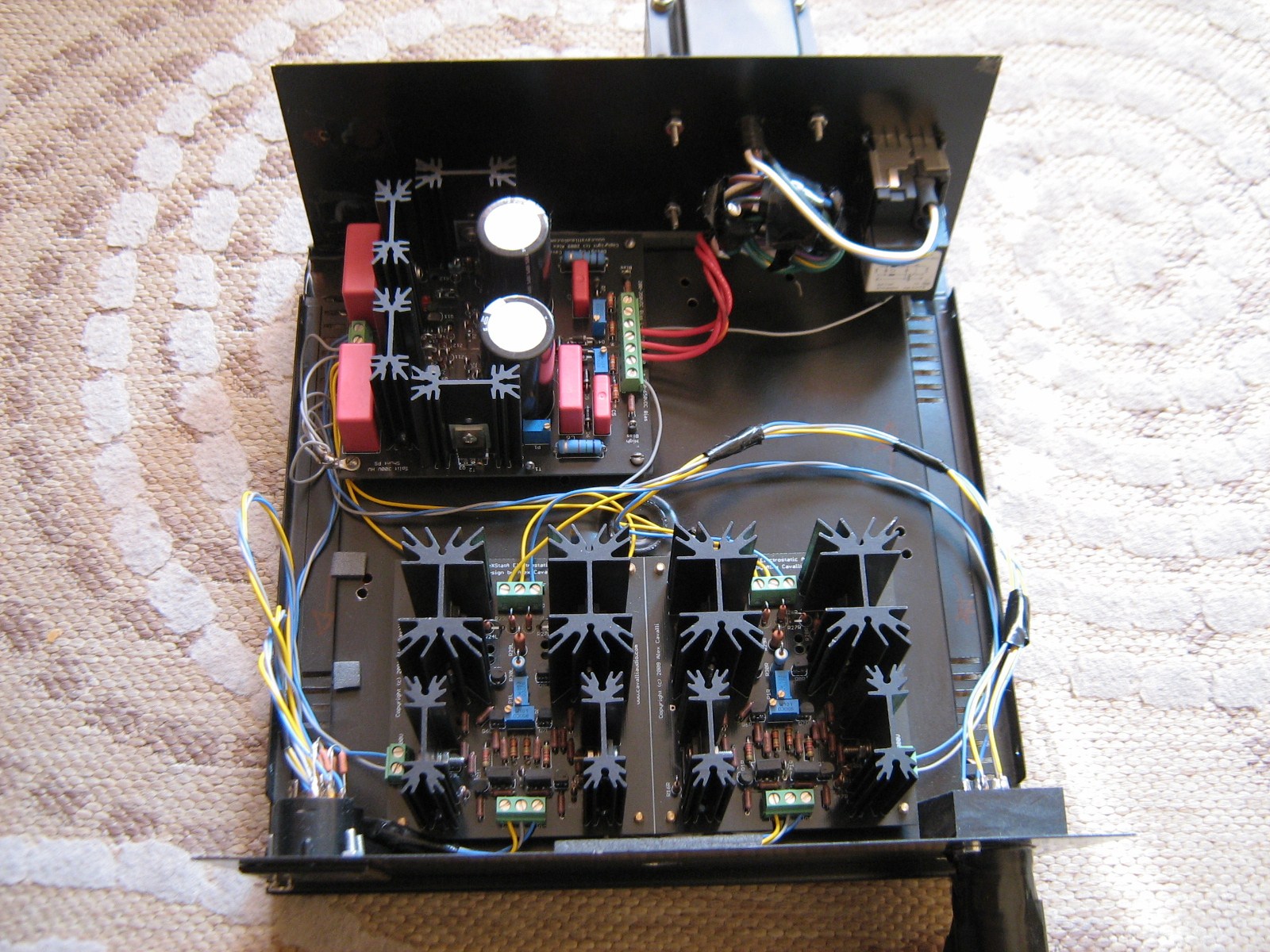
Starting towards the side next to the big WIMA caps, it should be a sandwich as follows:
screwhead
transistor
pad
heatsink
pad
transistor
flatwasher
lockwasher
nut
NOTE: Don't mount C3 & C4 until after you get the trans and heatsinks in place, or it may be difficult to keep the screwhead from spinning when tightening the sandwich of parts.
As far as orientation of the trans goes, you need to pay attention that the dot on the transistor is on the same side as the little dot on the silkscreen.
Quote:
Use a flat washer between the tran and the lock washer & nut.
Starting towards the side next to the big WIMA caps, it should be a sandwich as follows:
screwhead
transistor
pad
heatsink
pad
transistor
flatwasher
lockwasher
nut
NOTE: Don't mount C3 & C4 until after you get the trans and heatsinks in place, or it may be difficult to keep the screwhead from spinning when tightening the sandwich of parts.
As far as orientation of the trans goes, you need to pay attention that the dot on the transistor is on the same side as the little dot on the silkscreen.
Quote:
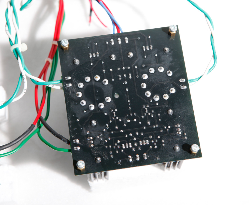
Thank for your response, Al. I should have waited with my post, however, as I now have another question. It's about the Q5, Q6 and Q7,Q8 transistors. All four of them have some sort of ID printed on one side. When I mount them to the heatsinks with this ID facing out (i.e., away from the surface of the heatsinks), their pins are too far apart to fit into the PS board. If I reverse them and so that the printed ID sides are both facing towards the headsinks, their pins are too narrow to fit into the PS board. (I checked this twice and believe I am right about this.) So, how do these transistors get mounted?
EDIT: Also about transistors. The mounting surfaces of some are made entirely of plastic and the special washer that comes with the Aavid mounting kit does not fit into their mounting holes. Should I place a regular flat washer between the screw and outside surface of these transistors? Also, I believe I heard somewhere that you don't need to use the Thermasil pads between the insid" surface of these plastic transistors and the heat sink. Is that true or should I use the pads no matter what?


