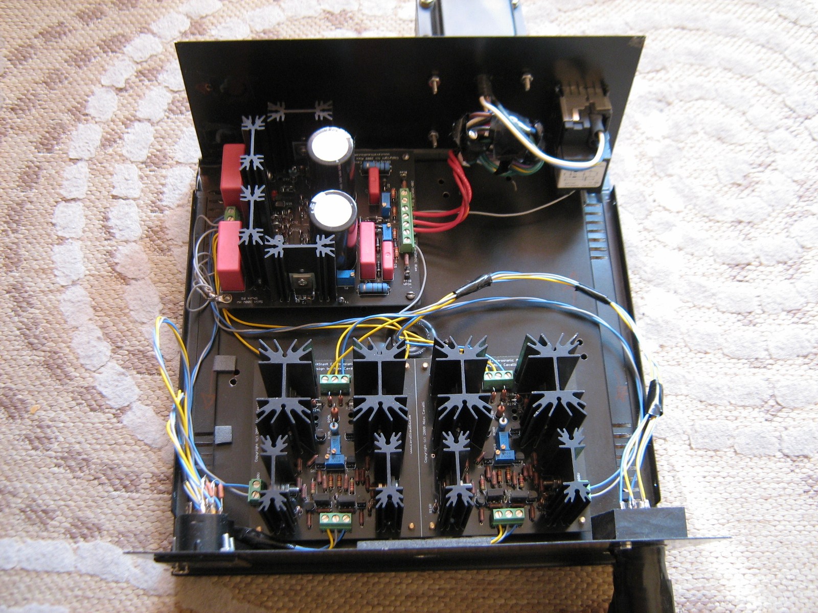
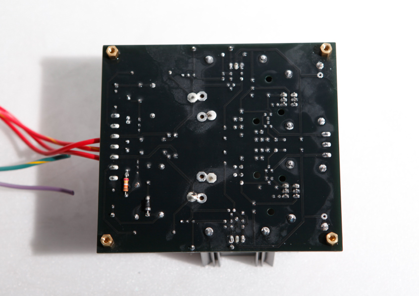
RH1 and RH2 are on board. AC measurements for the two output terminals are .10mA and .08mA. Output terminals to ground are .12mA AC and .11mA AC. (Please excuse the sloppy wiring. Things will be much neater after I'm up and running.)
Each heater terminal block needs one leg of the heater secondaries. As it's wired now, you have only one side of the heater winding coming in to each tube.
You would need two of those 4-position insulated term blocks. One for each lead of the heater secondary. Bring the lead from the heater secondary into a block, then jumper it down to hit the other three positions. Then one lead from that term block goes to the same side of each heater term block on the amp boards. Repeat the procedure for the other secondary heater wire and you will have complete heater circuits.
EDIT: Beefy is also correct, the grounding is not correct. Ground from the PS goes to the main SG point at the top of your chassis. The two SG points on the amp boards need to be brought to that star ground point too.
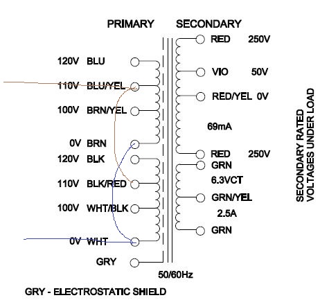
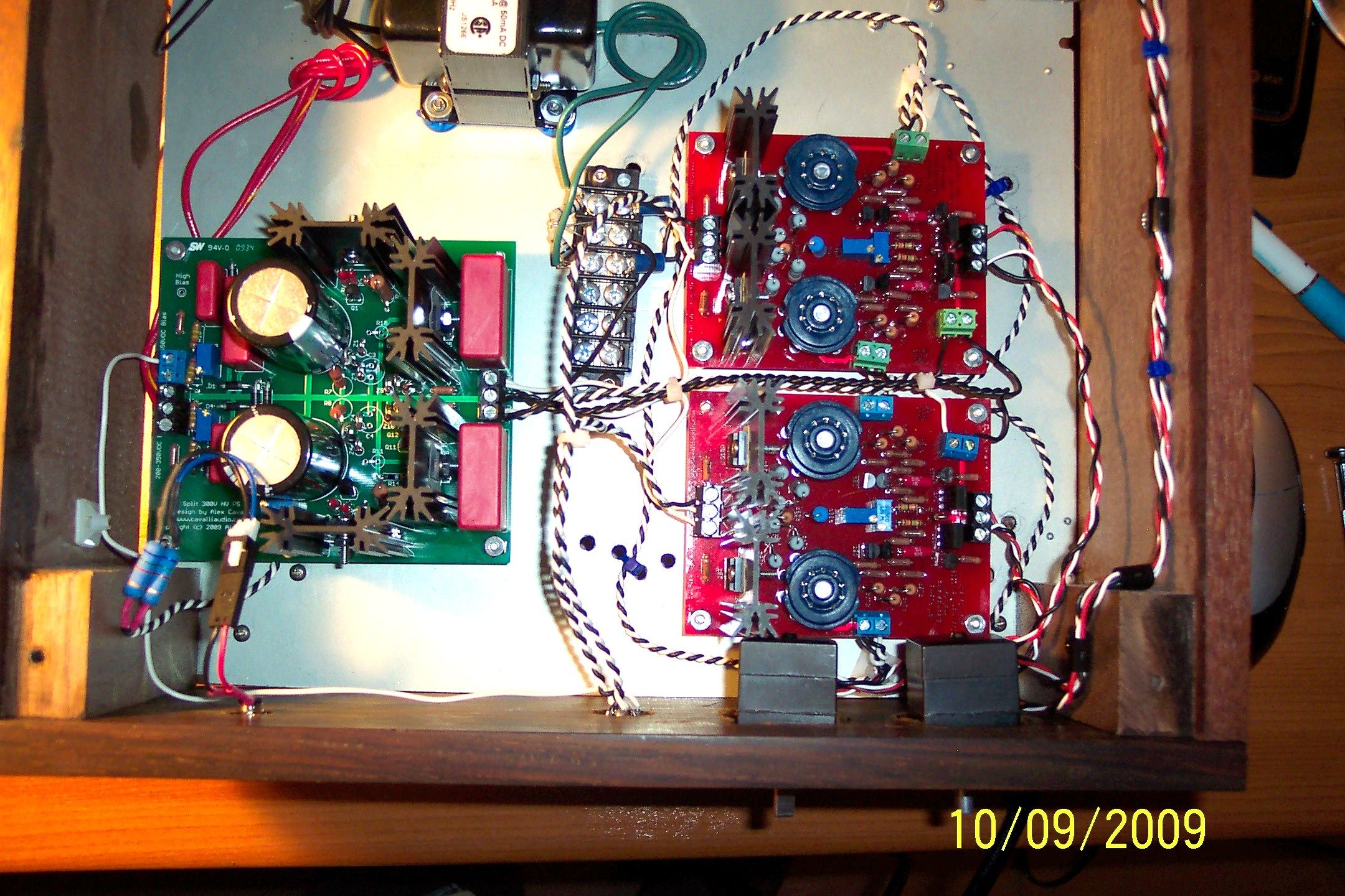
Disconnect the purple twisted pairs from the central terminal block. What you want to do is connect one side of each pair to one of the green wires from the transformer, and the other side of each pair to the other green wire.
Right now you have the extra little loops of green wire in the terminal block which is providing two connection points for each side of the AC heater winding, but those are not really necessary unless you can't fit all four purple wires into a single connector.
Basically you want the heaters to all be connected in parallel.
Yes, Beefy is correct. The grounding needs to be fixed up as well. You need to have a green ground wire on each board all going to your 'star ground' connection with the screw. Right now you have a ground wire going from the power supply to one amp board. Each ground connection on each board should go to the screw in the upper right.
The grounding error and how to fix that seems clear. It also seems that BoilerMakerFan and TimJo are telling me essentially the same thing: I should have two pairs of four gang interconnects with one of the secondary transformer wires connected to each interconnect and then three jumpers from it to the other three ports on that side. Wires on the other side of each interconnect go to the heater terminal connectors. All wires from one interconnect go to the same side of the heater terminal connectors (say, the right connector looking at the side where the wires are inserted). The wires from the second interconnect then get inserted into the other side of the heater terminal connectors (left in my example). Yes?
TimJo is right, you probably don't need a new term block.
Using your pic I quoted. Let's number the top heater points in the term block 1-4, L-R.
Take the wires out of point 1 and separate them. One wire goes back into point 1 and one needs to go into point 3. The wires from 2 need to be split and go into 2 and 4. The wires from 3 need to split and one goes to point 1 and the other goes back into 3. The last wires are pulled from point 4 and split then individually inserted into point 2 and 4. This will put 2-wires in each term block point, but they are split and the heaters are complete.
If that makes sense, it will get your heaters up and running.
EDIT: One final observation, and this is just me, but I would use metal screws and nuts to mount the transformer. Just in case it ever developed an internal short, the frame would be grounded and it will blow the fuse and not be a shock hazard. Also, the tops of the PS caps are live, so if your arm or a tool rests across them with power, it will bite you. I think Beefy or somebody else recommended putting electrical tape over the metal end caps to protect you while doing the testing and such.
Simpler to me is always better. I will stick with the four gang interconnect, rearrange the purple wires, fix the ground and get back to you all. Thanks very much, gents!
This site uses cookies to help personalise content, tailor your experience and to keep you logged in if you register.
By continuing to use this site, you are consenting to our use of cookies.