eXStatA Build Thread II
Apr 24, 2012 at 3:27 AM Post #542 of 588
contact me via IM
 
Apr 24, 2012 at 11:33 PM Post #543 of 588
One of these days I'll get my stuffed hybrid boards installed in my case.  After that then I'll have an SS amp board set and full BOM of parts for the amp section for sale (but I think the PSU board was used to fix my old amp - I have to check).  If the hybrid boards don't work then EVERYTHING might have to go, since I can't build the SS amp.
 
Mar 5, 2013 at 3:32 AM Post #544 of 588
It's been too quiet arround here for too long :wink:
 
 
My exstata is making trouble since yesterday.
 
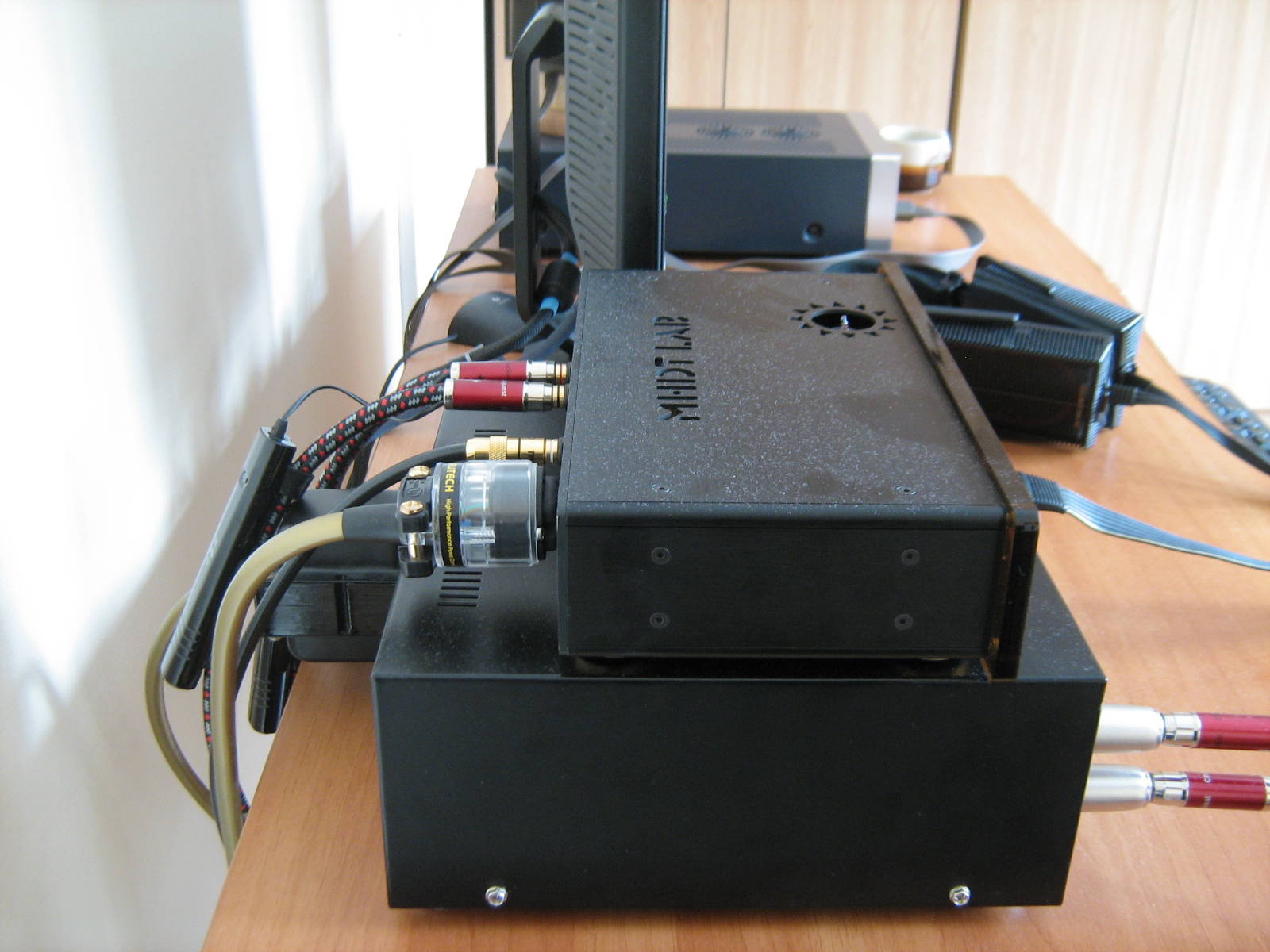
I took out the boards to change some of the input wiring in the case.
(Source selector and loop out stuff)
 
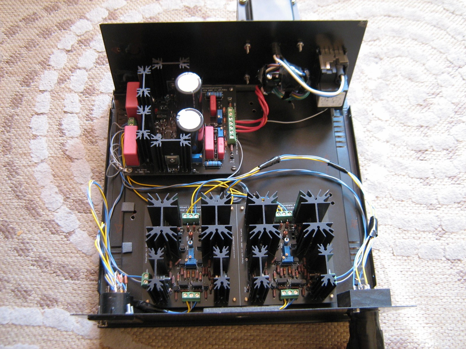
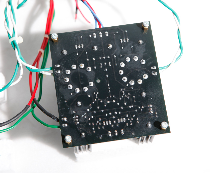
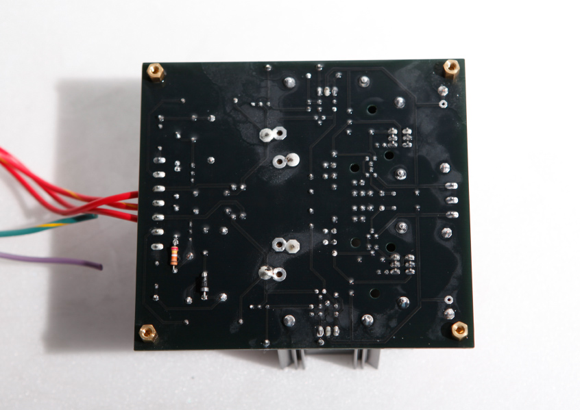
I also cleaned the boards softly with a soft paint brush to remove some dust.
 
The I installed everything back and began with the initial check.
 
 
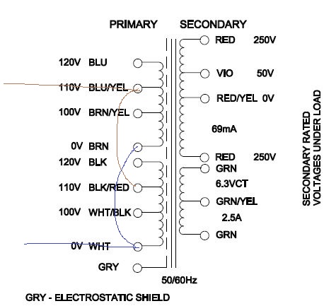
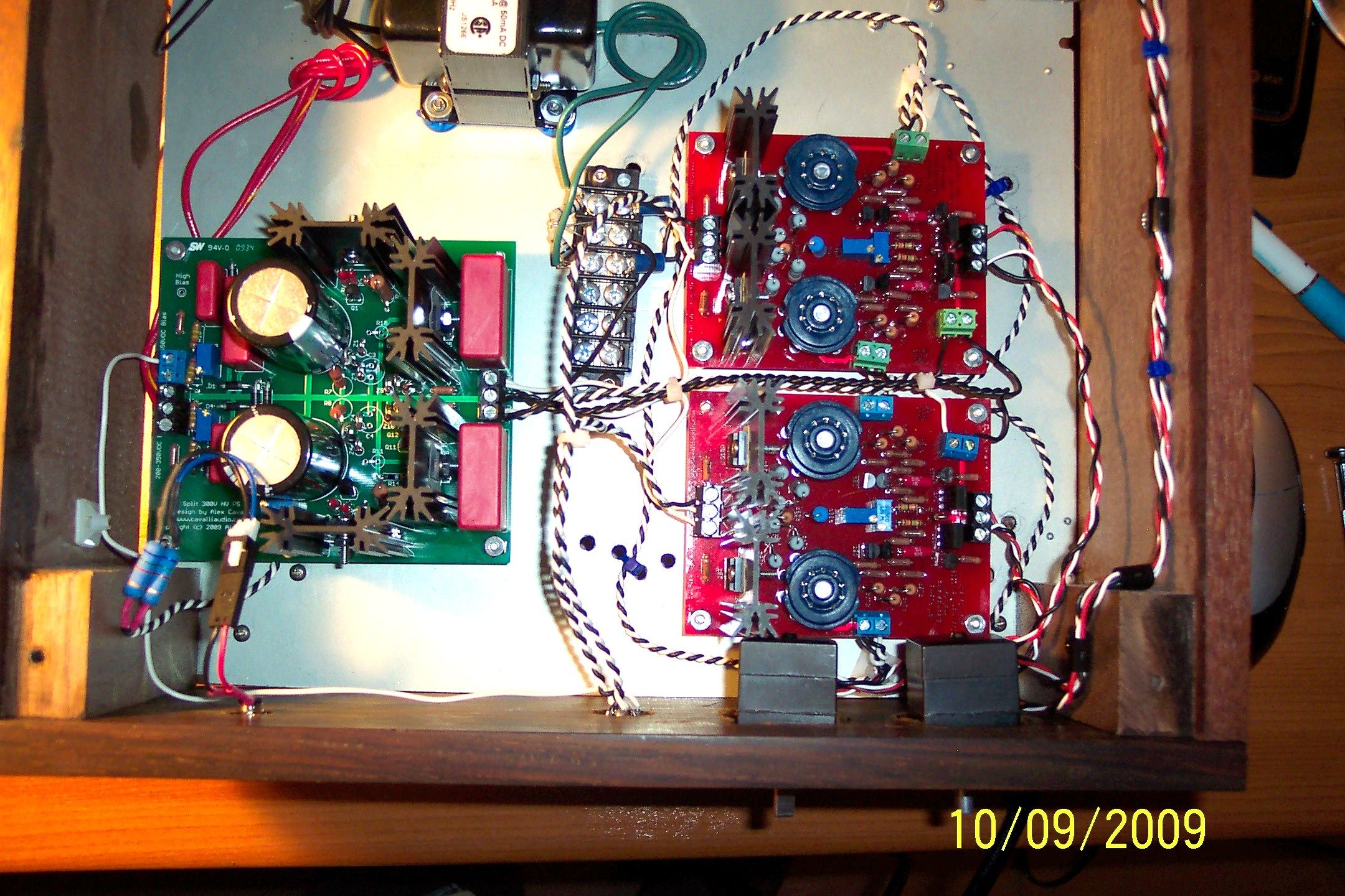
Power supply is ok - but the two boards are showing high offset values!
Everything worked perfectly before, now I'm unable to get the voltages
down close to 0V before the end of the trimpots is reached.
 
One board is showing ~40V between + and -, the other one
shows more than 150V and rising (I switched off then).
 
 
So what the H*** is going on here?
I can't imagine having destroyed something with a paint-brush!
 
Mar 6, 2013 at 3:39 PM Post #546 of 588
We'll  -fixed it :wink:
 
One board defenitely had a problem - maybe due to dirt or whatever.
 
The other part of problem was me!
I mixed up the two trimpots - so this could not work.
 
 
Now it's sitting here at my desk, warming up and the voltages are ok.
 
 
Now let's hope I have not mixed up L / R channels somewhere im my wiring :-D
 
Mar 29, 2013 at 6:45 PM Post #547 of 588
I took my solid state exstata out to do some measurements and now I am a bit worried about what I saw. I have been using a function generator which has a bigger output voltage swing than the ipod I usually use (around 1V for one, 2,5V for the other). At full output (which was something like 40 or 50V peak to peak) the red diodes in the power supply aren't lit as they should ; One goes blank while the other oscillates.

So here are my two questions. How normal is it for the diodes in the power supply to act this way ? And secondly, how come the amp starts to behave  weirdly at only 50V peak to peak ? Have other builders experienced this (should I question my own building skills ? ) ?
 
(I might to have to check again, but I really think it is 50V peak to peak. Coming from a ±300V powered amp it seems a bit low. Should the exstata be powered with something like a 10V source ? )
 
Mar 29, 2013 at 7:08 PM Post #548 of 588
From memory, those LEDs light up when current is running through the shunt regs. So I wonder whether as the output voltage goes up, current consumption increases, and your PSU is dropping out of regulation.

If this is the case, increasing the current through the first stage of the PSU by a small amount might help.
 
Mar 30, 2013 at 2:49 AM Post #549 of 588
Thank you Beefy. So toying with P1 and P2 in the power supply it is
biggrin.gif
I hope it is going to be tough enough to handle it.
 
Edit : I checked T1-T2 and T3-T4 in the power supply. It is in the range Alex Cavalli suggested. Another thing, I plugged the eXstata into my otl tube amp to have moar input voltage (up to 6VAC) so that the output delivers around 600vac max. The red diodes in the power supply are not oscillating as I described before. I have not a clue of what is going on ... maybe the fact of the function generator being a monochromatic source plays a role ?
 
edit2 :  I am pretty sure I wasn't careful enough with ground sharing.I probably shorcut one of the output while measuring with the oscilloscope which lead to stupid results ... I will have to try again to make sure it was indeed my own stupidity ...
 
Jun 19, 2013 at 5:26 PM Post #550 of 588
My exstata is showing some strange behavior this evening.
 
I have a kind of humming/buzzing sound, changing in toneheigt over time.
It disappears are becomes at least almost unhearable when I touch
the case or the metal parts of the cinch connectors.
 
It's only the right channel.
 
What might that be?
 
Aug 1, 2013 at 8:18 PM Post #555 of 588
Thanks sachu. I just traced the wiring on the 'phones (ESP 950's), and found that the amp jack diagram in the second link has the L- and R- reversed.
Pin 4 should be R-, pin 5 L-. That's what had me baffled. I had to use a very small needle to pierce the cable so I could verifiy that they were switched
on the diagram.
 

Users who are viewing this thread

Back
Top