You are using an out of date browser. It may not display this or other websites correctly.
You should upgrade or use an alternative browser.
You should upgrade or use an alternative browser.
Electrostatic ear speaker DIY'ers suppliers list
- Thread starter Muamp
- Start date

janosch simon
Head-Fier
btw dave you dont have any cnc g-code of the boards you made at hand? 
cheers janosch
cheers janosch
Hi janosch,
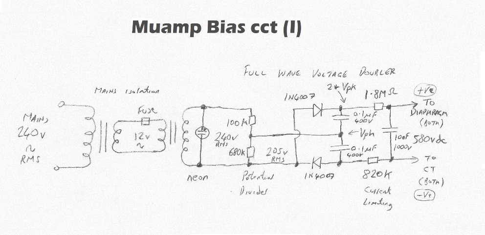
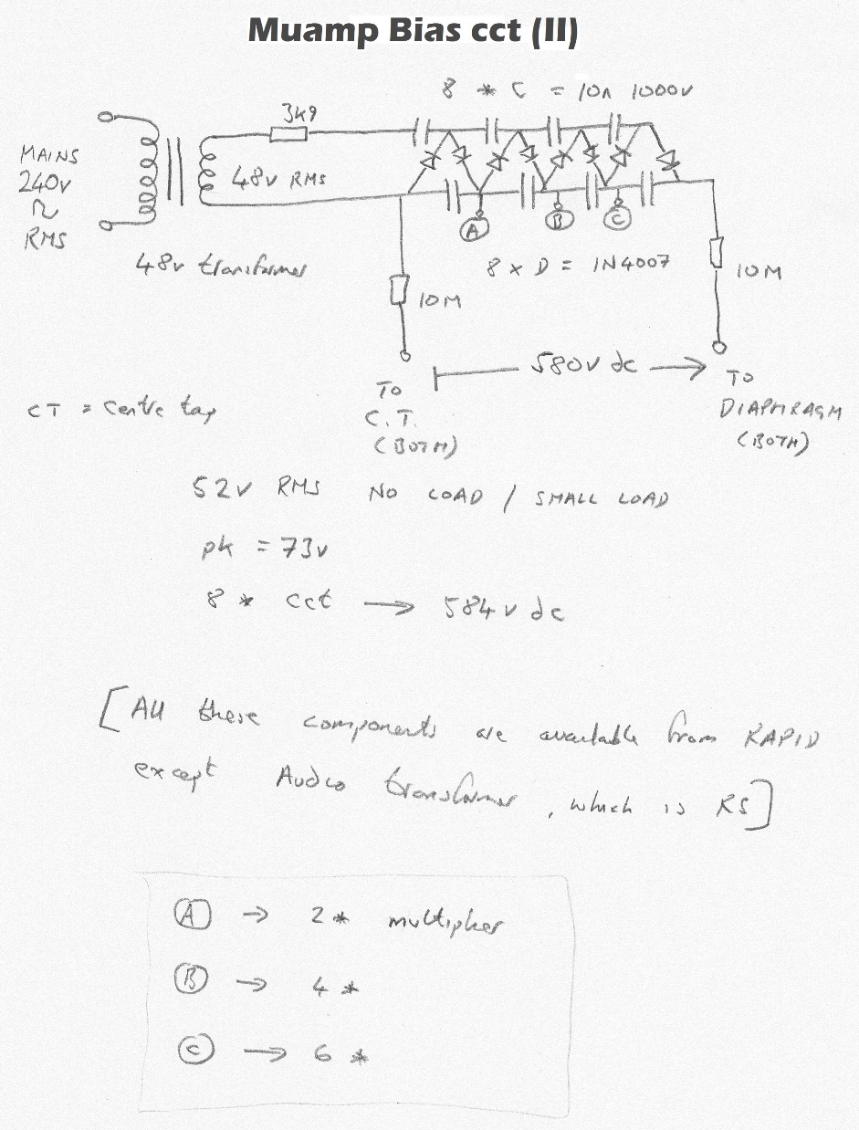
I produced CNC generic g-code for the TubeCAD energiser boards, but I didn't make PCBs for the transformer / bias ccts. These were designed and made before I had a CNC, so I used patch board for the bias ccts above, since they are basic and can be made on patch board easily.
BTW, I don't recommend you make the TubeCAD energiser. There are other DIY energisers which are far better and easier to make.
David.
Last edited:
janosch simon
Head-Fier
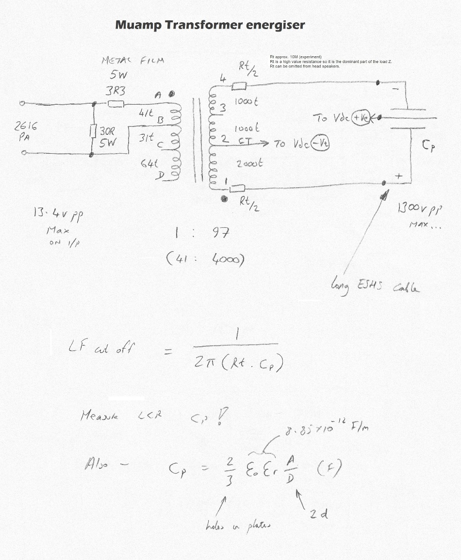
hey david i got transformer energiser running but i have a question in regards to Rt what would happen when i leave them away? this is only for the cut off frequenz right?
cheers janosch
cheers janosch
Hi Janosch,
What a brilliant question!
Rt always was an item of contention, and quite often omitted from amateur and professional designs.
The ESL panel is predomanently a capacitive load (Xc). Rt is included to make the load predomanently resistive, that is R to be bigger than Xc at the frequency where Xc is at it's greatest.
The idea of Rt (Rt/2 on both sides) is to make the predomanent part of Z - resistive, equal on both sides where Rt/2 is as close to the transformer terminals as possible.
David.
I have included a quote from Frank Verwaals brilliant book "The Design of Electrostatic Loudspeakers" which covers the Rt section. This (free) book seems to be no longer available.
9.3 Realization of Current Drive
To realize a constant (that is: frequency independent) drive current, we can consider the
use of an amplifier having a current output.
The output of such an amplifier behaves as an ideal current source.
Connecting the stators of the loudspeaker to an ideal current source, however, creates
the problem that the dc voltage across the ESL is not fixed.
This means that a pure current drive is not possible: for low frequencies the current
source behavior must always change into a voltage source behavior in order to fix the dc
voltage.
A practical way to realize a constant drive current at audio frequencies is to take a high
voltage audio source and place a large resistor R in series.
The voltage source could be a normal audio amplifier with a voltage output, followed by
a step-up transformer, or it could be a custom designed high voltage amplifier.
In practice we split the series resistor into two resistors, each with value R / 2 , to
preserve the symmetry of the circuit.
For audio frequencies, the impedance of the loudspeaker, which is almost purely
capacitive, is low enough that the current is completely determined by the transformer
output voltage and the total series resistance R .
For low frequencies, the impedance of the ESL increases to the point that it becomes
larger than the resistance R . Below that frequency the total impedance doubles with
each octave that the frequency drops. Therefore the drive current rolls off at a rate of
6 dB/oct and a constant drive current can at those low frequencies no longer be
maintained. Due to the decreasing drive current, the frequency response of the
loudspeaker drops as the frequency decreases.
Appendix III gives the formula that describes the -3 dB corner frequency of the roll off.
We try to design the loudspeaker such that the corner lies below the lowest frequency
we want the ESL to reproduce.
At dc, the plates connect through a resistance to the step-up transformer and that nicely
fixes the dc voltage across the plates to zero volt.
Example.
Suppose that the amplifier delivers a voltage of 10 Vrms and that the step-up ratio of the
transformer is 1:100. The transformer output voltage is then 1000 Vrms.
If the total series resistance is for example 1 MΩ (2×500 kΩ), the drive current for a
sufficiently high frequency is 1000 V/1 MΩ = 1 mArms.
Suppose further that the area of the loudspeaker is 1 m2 and that the distance between
the stator plates is 3 mm.
Disregarding the holes in the plates the stator capacitance is then 3 nF. You will find the
formula that you need to calculate the stator capacitance in appendix IV.
A large portion of the stator area, say 50%, consists of holes.
The metal area lost to these holes leads to a reduction of the capacitance, but the
reduction is less than proportional to the lost area.
The actual capacitance will therefore be somewhere between 1.5 nF and 3 nF.
Let’s assume that the stator capacitance ends up being 2 nF.
The frequency where the drive current starts to roll off is determined by the RC product
and is 80 Hz.
(David) These figures are for large full range floor standing ESLs, but the theory is the same.
Don't get bogged down by this,...... The bottom line is that (in theory) by having a large Rt resistance, the LF roll off is improved.
In practise, I have tried leaving out Rt and it didn't make a hugh audible difference....... but I still included it anyway as Franks theory illustrates.
Ball park figure have Rt at about 10M ohm. ..... experiment and tell me if you think it makes a difference.
I believe Stax never bothered having Rt..... but many professional designs didn't / don't.
janosch simon
Head-Fier
phew i thought its a stupid question hihi nice as my sound is still far from OK i need to remove as many possible errors as possible. at work we have a measure device that showed me the capacity between stator and stator of 49pF and between Stator and Membrane 60pF if my math is then not completly off i would get and Rt of 920k Ohm or 750k Ohm will try tomorror an Rt/2 of 475k and 375k
and report")
my biggest problem is that i have to put the stators facing outwards. if i put them next to the spacer no matter how low i put the output of the amp and the bias it roars the other way round i hear sound but very very quiet hmhmhmhm lot of work to do
cheers Janosch
and report
my biggest problem is that i have to put the stators facing outwards. if i put them next to the spacer no matter how low i put the output of the amp and the bias it roars
the other way round i hear sound but very very quiet hmhmhmhm lot of work to do cheers Janosch
49pF stator to stator is about what I would expect.
Rt at about 1M Ohm is reasonable, although my calculation shows that your Rt should be higher; Fr = 1 / (2 Pi Rt Cp).
The hum, could possibly be mains hum from the bias cct? Possibly use bigger values of R on the bias cct. Although "roars" not sure.... Also - check that the excess membrane of the diaphragm is completely removed from the outer rim of the spacer, not shorting to the stators. Scrap the outer edge with a sharp blade or even better a hot soldering iron to burn any fragments away from the outer edge.
The photos of your stators on Wachara's thread look good.
David.
Last edited:
100VoltTube
100+ Head-Fier
- Joined
- Jul 29, 2016
- Posts
- 229
- Likes
- 39
It's right here:This (free) book seems to be no longer available.
http://home.kpn.nl/verwa255/esl/ESL_English_2011.pdf
By the way, it's a fascinating read, and totally worth it for anyone interested in the theory behind ESLs and ES headphones. It is also very technical and sometimes hard to understand.
Last edited:
janosch simon
Head-Fier
nice read today was a great day first succsess with my Phones YAY
David two questions:
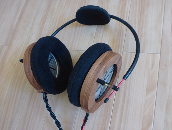
- regarding your headband is that just a wire?
- what kind of kabel you use?
i just finished my first case for a real test cant wait
cheers janosch
today was a great day first succsess with my Phones YAYDavid two questions:
- regarding your headband is that just a wire?
- what kind of kabel you use?
i just finished my first case for a real test cant wait
cheers janosch
1. My headband on the first 4 Muamps is 2.2mm steel rod. On Muamp#5 it is 2.5mm. The rod is bent around a circlular former and then covered in silicon rubber tube.
2. The cable is Rapid 01-0605 extra flex.
David.
2. The cable is Rapid 01-0605 extra flex.
David.
janosch simon
Head-Fier
HMMMM thx David but then its not adjustable hm but on the the other hand its only for me
i still have problems with uhu por glu are you useing the same? i cant get an even thin coating with it will try to get 3M 4693 mentioned in the book from from this tread cheers janosch
i still have problems with uhu por glu are you useing the same? i cant get an even thin coating with it will try to get 3M 4693 mentioned in the book from from this tread
cheers janoschHi Janosch,
You said "HMMMM thx David but then its not adjustable hm but on the the other hand its only for me"
The headband IS fully adjustable in all aspects (height, angle, rotation, swivel) as the photos show.
Muamp#5
Muamp#4 and Muamp#5
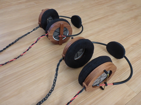
This headband is my own design which I have used for all Muamp ESHS's. You could also come up with your own design of headband...
David.
You said "HMMMM thx David but then its not adjustable hm but on the the other hand its only for me
"The headband IS fully adjustable in all aspects (height, angle, rotation, swivel) as the photos show.
Muamp#5
Muamp#4 and Muamp#5
This headband is my own design which I have used for all Muamp ESHS's. You could also come up with your own design of headband...
David.
janosch simon
Head-Fier
hehe David i will just finished my first pair and next week i hope to get the mylar foil from the companie around your corner also made the first housing for the earphone cant wait to test no with the testbench energizer and the way to thick foil it has a very pleasent sound
cheers janosch
just finished my first pair and next week i hope to get the mylar foil from the companie around your corner also made the first housing for the earphone cant wait to test no with the testbench energizer and the way to thick foil it has a very pleasent sound cheers janosch
Users who are viewing this thread
Total: 2 (members: 0, guests: 2)
