All along the way, dsavitsk kept suggesting the Audience Auricaps. I thought they were too expensive and that a hidden treasure could be found in cheaper caps such as the CDEs. Of course, I'm not a cut-and-dry objectivist, but I still have a developed prejudice against
voodoo capacitors.
He convinced me try a set, though, and while were investigating other potential tweaks in the prototype, I purchased and received a couple of the Auricaps. Wow! Full body, more detail, superlative dynamics, etc. I was sold and claimed the Auricap XOs as standard from then on. Auricaps were not
voodoo!
After messing around with the CDEs and then installing the Auricaps, I noticed that there were definitely differences in volume output, depending on the capacitor matching. It's not as much as with mis-matched tubes, but it was still audible. So, I began with matching the capacitors in using Auricap XOs installed in the T4:
These caps are all spec'd at 4.7uf, so you can readily see the difference in the Fluke 179.
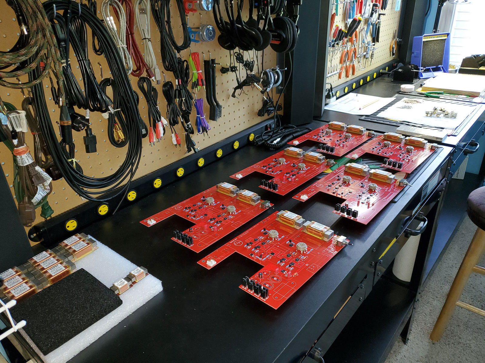
For this set of six T4s, I had ordered 20 Auricap XOs. Here they all are with measurements labeled on the bottom of the caps:
As you can see, they vary from a low of 4.79uf to a high of 4.86uf. Matched pairs were selected and I proceeded with installing them in the PCBs.
The Auricaps are different than most film caps in two ways:
- They specify a shield and which direction it should face in the circuit (faux polarity).
- They use double leads on each end!
They solder the double leads themselves from the factory, but leads on caps are always longer than needed. They are also longer than the minimum that causes trouble, so cutting them was no choice. It always scares me though, because you cut too much and you're up the creek. I had long ago documented the proper length for the T4, however (with a generous safety factor).
Here's a pair ready to be installed with the leads cut to proper length:
With caps this big and flexible leads (even if not), it takes more than just soldering them into place to keep them secure. To the right in the pic above, you can see four pieces of double-sided ultra-high-bond 3M tape. This stuff is clear, 2mm thick, and used in bonding materials in the aviation industry. So, it's not trivial tape.

I use two pieces of tape per cap, placed lengthwise on opposite sides of the capacitor centerline on the PCB. After soldering them in place, I press down firmly on the cap, where the curvature touches the bare PCB right on the centerline, but is making contact with the tape on both sides of the centerline as in a saddle, so to speak.
This shot shows the tape in place at both capacitor positions, with the secondary film still in place on top of the tape:
And with the caps installed (double leads in separate pads and soldered separately):
The above is actually an improvement over this version of PCBs. After the first T4s were sold, I contacted Doug to order more. He asked if there were any changes that were needed. I told him we needed four pads for each parafeed capacitor, because of the Auricap double leads. In previous builds, I wrapped the stripped portion of one lead around the stripped portion of the other lead, leaving a knot of soldered lead above the PCB pads. Although functionally equivalent, it was an added hassle for me in building. This was a more straightforward improvement.
Not so simple for a capacitor install, huh? At least it is light-years simpler than those four Mundorfs in the T3.
One other improvement was made in this batch of PCBs - an extra mounting/standoff hole near the power rectifiers. You'll see that in detail with posts about the casework assembly.


 No good deed goes unpunished. This caused me so much grief from customers that I quickly stopped including a spare fuse.


")


