Dr.Meier's Cross-1 discussion.
May 4, 2006 at 11:52 AM Post #301 of 334
Quote:

Originally Posted by sphinxllama
Oh, now I got it.

Shame on me, but I concentrated on the second picture because didnt know what all the numbers are for. Should think,look first and then write!

Thanks


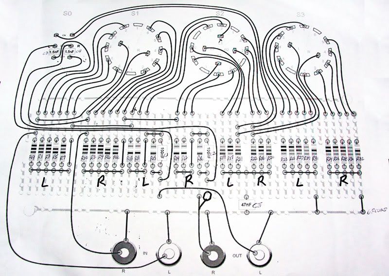
The second picture is great for figuring out where to hook all of the wires from the switches and jacks. Double check it against the schematic in the third picture and you should be good to go.

Good Luck!
 
May 5, 2006 at 4:59 PM Post #302 of 334
Could someone who has built and cased their unit confirm to me that the rotary switch alignment pins need to be ground down?

I know this is a no-brainer but it never hurts to ask, especially since the fit of the mechanical parts is so critical here
biggrin.gif
 
May 5, 2006 at 5:09 PM Post #303 of 334
Quote:

Originally Posted by NeilR
Could someone who has built and cased their unit confirm to me that the rotary switch alignment pins need to be ground down?

I know this is a no-brainer but it never hurts to ask, especially since the fit of the mechanical parts is so critical here
biggrin.gif


just like on Meier's website; I double checked the signal path to make sure

switchesprofile.jpg


What do you mean by "ground down?"
 
May 5, 2006 at 5:28 PM Post #304 of 334
There is a small round pin that sticks out parallel to the switch shaft. It is at 3 o'clock on the image you linked. That is an alignment pin, intended to be spotted into a hole in the panel. It ensures that the pot won't rotate in the panel and the index mark on the knob won't drift. When board mounted, it doesn't add much value except that it prevents the device from being mounted/oriented incorrectly. Since we do not have alignment holes in the panel, I assume people are grinding them down, just like most people do with Alps RK27 pots, which have the same type of alignment pin.

I don't think you will find that pin on the schematic
k1000smile.gif


Quote:

Originally Posted by Teerawit
just like on Meier's website; I double checked the signal path to make sure

switchesprofile.jpg


What do you mean by "ground down?"


May 5, 2006 at 5:35 PM Post #305 of 334
Never mind, the instructions explicitely state that the alignment pins are to be removed.

Regards,
Neil

Quote:

Originally Posted by NeilR
There is a small round pin that sticks out parallel to the switch shaft. It is at 3 o'clock on the image you linked. That is an alignment pin, intended to be spotted into a hole in the panel. It ensures that the pot won't rotate in the panel and the index mark on the knob won't drift. When board mounted, it doesn't add much value except that it prevents the device from being mounted/oriented incorrectly. Since we do not have alignment holes in the panel, I assume people are grinding them down, just like most people do with Alps RK27 pots, which have the same type of alignment pin.

I don't think you will find that pin on the schematic
k1000smile.gif


May 5, 2006 at 6:20 PM Post #306 of 334
oh....ground as in grind.....that makes more sense. I thought you were referring to ground as in voltage = 0 V.
biggrin.gif
 
May 6, 2006 at 2:45 AM Post #308 of 334
Quote:

Originally Posted by Ballooshi
Teerawit,

Did you get your MetCal yet? Ready to start your builds?


Ya I got the MX-500 station. I've used it alittle so far (PINT and CROSS-1), but I need to order more parts before they are finished.
frown.gif
 
May 6, 2006 at 3:02 AM Post #309 of 334
Quote:

Originally Posted by Teerawit
Ya I got the MX-500 station. I've used it alittle so far (PINT and CROSS-1), but I need to order more parts before they are finished.
frown.gif


Nice rig! ($$$)

I just got a Hakko 937, almost ready to start my builds.

Are you also going to build the HA-1?
 
May 6, 2006 at 3:12 AM Post #310 of 334
Quote:

Originally Posted by Ballooshi

Are you also going to build the HA-1?


Yeah in a few months
biggrin.gif
 
May 7, 2006 at 12:51 PM Post #313 of 334
Quote:

Originally Posted by sphinxllama
OK got i#t


Glad you got it... you edited your post before I had the chance to answer your questions!

Perhaps the new pic I posted will clear up any questions anyone else might have.

Hopefully everything works OK... have you listened to it yet?
 
May 7, 2006 at 8:35 PM Post #314 of 334
@Ballooshi

Thanks a lot for your tireles help till the end.

It runs now for only 20 minutes but my impression is that it works and it works really great. All the work was worth it!!! I am really impresed by this little box how it can rock my headphone.

580smile.gif
k1000smile.gif
(I think this is the best explanation!!!
smily_headphones1.gif
)

I can post some pics later if you want me too.

And thanks again!!!
 
May 8, 2006 at 12:35 AM Post #315 of 334
Just out of curiosity, anyone know or care to guess why a few resistors are mounted on the switch side (the front)? I don't see any physical obstruction preventing all of the resistors from being mounted on the rear of the board.
 

Users who are viewing this thread

Back
Top