Does anyone have the iPhone LOD pinout?
Sep 25, 2008 at 8:29 PM Post #62 of 259
Is it possible to open one of these and adjust the pins to have it become compatible with the 2G Touch/iPhone? Has anyone done this before?

dock-2black.jpg
 
Sep 26, 2008 at 12:55 AM Post #64 of 259
I did open an Apple-supplied iPod-to-USB cable, and there were the usual USB pins in their slots, but the rest of the holes were filled up with some sort of epoxy. Good thing those docks are so cheap, but I'm not sure whoever made that would fill the other holes with epoxy or glue. That is a glue-required dock, however. Is it possible? Sure. Is it worth the trouble? Most likely not.
 
Oct 2, 2008 at 6:18 PM Post #66 of 259
Has anyone confirmed that tying pin 11 to one of the ground pins in the LOD will activate the LOD for the second gen iPod touches?
 
Oct 18, 2008 at 1:55 PM Post #68 of 259
So the other day I opened up my iPhone 2G dock. I think what Apple did was print the board on three or four layers and cover it all up with the ground plane. I'm not sure what the dozen test points lead to, and I measured the different combinations of resistance between pin 11, 21 and ground and I didn't find anything conclusive. Here's a link to the datasheet for the HCF4098, a dual monostable multivibrator: linky.

IMG_3628.jpg


IMG_3629.jpg


IMG_3632.jpg


IMG_3633.jpg


Here's a link to the datasheet for the HCF4098, a dual monostable multivibrator: linky
IMG_3634.jpg


IMG_3636.jpg


IMG_3639.jpg


IMG_3645.jpg


IMG_3641.jpg


IMG_3642.jpg


Again, we find positions for DZ. I searched up acronyms for DZP like the ones in and around the iPod docks and all I got was "Double Zeta-Polarization Contracted Gaussian Basis Set." Anyone?
 
Nov 18, 2008 at 3:57 AM Post #70 of 259
@CanadaDude
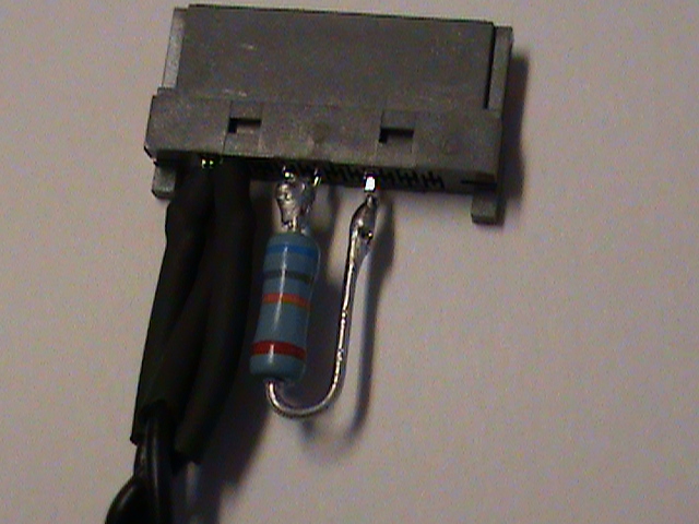
Yeah, zener for input/ESD protection or part of a simple voltage regulator circuit.

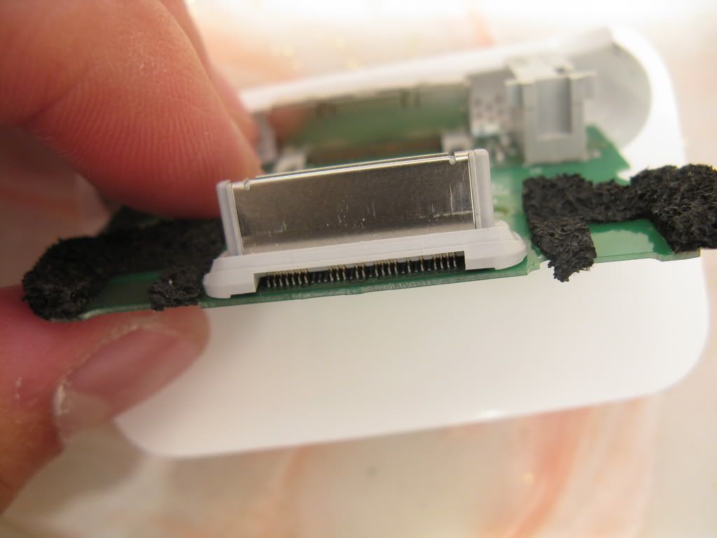
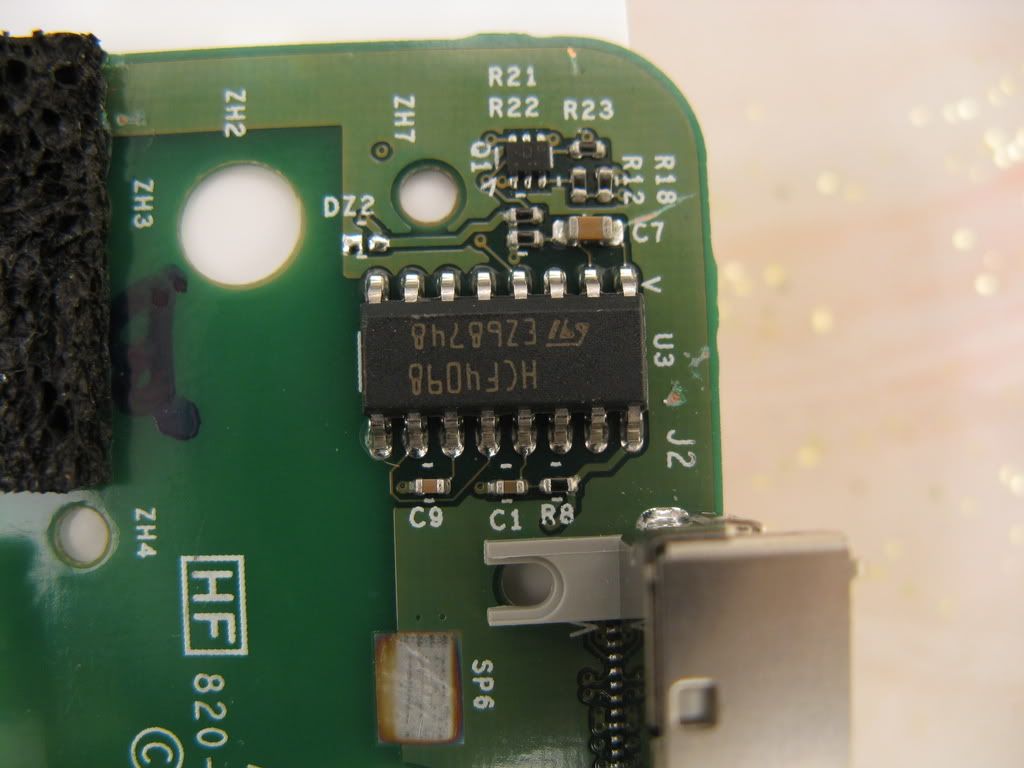
I'm still trying to find out how to keep the accessory message from coming up. I can't imagine why it's not on google. All I can find are stupid ipod values which obviously aren't the same. Assuming the values someone posted here are correct:

assume 1, 2, 15, 16, 29/30 are common.

pin21 to common = 375k
pin11 to common = 11.25M
pin21 to pin 11 = 11.65M

This makes me believe the circuit looks like this:

-------375k-------<--pin 21
|
|
------11.25M------<--pin 11
|
|
GND

Has anyone tried using 375k from pin21 to common? The pin21 to pin11 being 11.65Mohm, like another poster measured, makes sense because 11.25M + 375k is about 11.65M.
 
Nov 18, 2008 at 5:11 AM Post #71 of 259
Ok I just hooked up a 47k and a 330k in series for a combined value of 377k from pin 21 to pin 1 (common). I am not seeing any accessory message and I've tried it ten times now. I will need to get a probe to actually verify that there is continuity but I've triple checked my breadboard. So maybe this will let you use LOD without going into airplane mode. I'll build up my mono audio circuit again tomorrow and see what happens.
 
Nov 18, 2008 at 3:53 PM Post #74 of 259
I just checked. I put in the resistance you mentioned and indeed, it doesn't give me the accessory message. The flip side is that audio still comes out the speaker. Try again. =T
 
Nov 18, 2008 at 5:09 PM Post #75 of 259
But I don't think the line out is related to the accessory pin. I think I just tied pin11 to pin1 (gnd) and pin21 to pin11 with a 1k resistor last time and the line out worked. What did you do with pin11 this time?
 

Users who are viewing this thread

Back
Top