


sajunky
Headphoneus Supremus
Bringing IEMs to the dynamic range debate doesn't help. One things is sensitivity, the other is dynamic range.
Most of the numbers I see are with respect to sinusoidal tones. Is there any better metric presently available (as a whole analyser software package) to measure random signal fidelity and non linearities?One point to make here is that dynamic range does not equal fidelity. The argument has been raised on the thread that a 75dB dynamic range means no other equipment should need to exceed this figure. This figure does not account for the amount of granularity the human ear/bran can hear within that 75dB range. It describes a ratio of sound pressure levels that can be detected by a microphone, but not how small of a change between two pressures within that range can be detected & recorded.
At the recording end, the ADC used by the studio should be attempting to extract as much information on the exact amplitude of the analogue wave output from a microphone as possible – the fine detail of the sound source. The actual levels of a mic’s output will obviously be adjusted during mixing, so the goal from the conversion standpoint is to take samples as accurately as possible from an amplitude perspective.
The playback side of the signal chain should be at least as capable as the converters used at the recording end, as if nothing else it allows for one less area of potential error between the studio and the listener.
Considering the potential implications of, for example, digital volume controls and DSP within a DAC – particularly given the sensitivity of IEMS – any attempts to achieve as low a noise floor as possible should definitely be taken.
As the most recent post states, it is meant to be an introduction to the topic of D/A conversion and doesn’t attempt to cover every possible DAC architecture – instead, the aim is to explore the fundamental limitations of common D/A approaches, and next will go into how the Ring DAC improves on them.
Taking the case of a sign magnitude DAC, this approach will mitigate the zero crossing point error effectively (it does that quite well), but it does not eliminate similar issues with other multibit changes. With a 16-bit R-2R (sign magnitude or not), the following are a few examples of crossings which are still problematic:
… and so forth. These crossings are difficult with the R-2R approach because the sum of the current source errors needs to be closely matched to avoid correlated signal errors.
- 16383 – 16384 / 0011111111111111 – 0100000000000000
- 8191 – 8192 / 0001111111111111 – 0010000000000000
- 4095 – 4096 / 0000111111111111 – 0001000000000000
On resistor value tolerances, with an R-2R approach the crucial point to consider is that any error manifests as an error which is correlated to the audio, which perceptually is just about the worst case scenario – distortion.
Failure rates of components is a separate conversation, unrelated to dynamic resolution or converter types.
In a flat linear system, dynamic range is effectively the same as SNR. If 75dB dynamic range was sufficient, that would imply a 75dB noise floor would be okay – which is definitely not the case. One could actually make a 14 bit DAC to fit a 75dB range, but the noise floor of said DAC would be 78dB.One things is sensitivity, the other is dynamic range.

|
Stay updated on dCS at their sponsor profile on Head-Fi.


|


|
|
Stay updated on dCS at their sponsor profile on Head-Fi.
|
Wow. It looks much closer to a multi bit PWM than an r2r at this point. A feedback loop would make it close to a delta Sigma. Im curious what classification this will fall into in the realm of r2r, delta Sigma and pwm dacs.Part 4 – The Ring DAC
How can the issues described previously with Ladder DACs be resolved? What would a DAC designed from the ground up to effectively de-correlate errors in the DAC itself and remove the resulting distortion look like? That is where the dCS Ring DAC comes into play.
The Ring DAC is the proprietary DAC technology found inside all dCS DACs. On the surface, the Ring DAC may look like a Ladder DAC. There is a latch and a resistor for each current source, and these current sources are fed to a summing bus. The key difference between the Ring DAC and Ladder DACs however, is that the Ring DAC uses current sources of equal value. This is what is known as a ‘unitary-weighted’ or ‘thermometer coded’ DAC architecture. Additionally, the Ring DAC does not use the same current source(s) for the same bit every time. There are 48 current sources within the Ring DAC, all of which produce an equal amount of current. The Field Programmable Gate Array (FPGA) controlled nature of the Ring DAC allows the sources to be turned on and off in such a way that any component value errors are averaged out over time. Firing the same bit three times on the Ring DAC might give one output slightly high, the next slightly low, the next somewhere in the middle, as opposed to outputting the sample slightly high every time, or slightly low every time (as seen in a Ladder DAC, for example).
It takes a considerable amount of signal processing power and know how to optimally operate a thermometer coded DAC, but the benefit with this approach is that it almost entirely removes the linear distortion from the signal (bear in mind that the highly artificial distortion many DACs produce is very noticeable to humans and has a negative impact on perceived sound quality).
The Ring DAC process may be thought of as decorrelating errors. Background noise (an uncorrelated error – one which is not linked to the audio signal itself) is very prevalent in nature, whereas artificial distortion (a correlated error) is not.
This results in the Ring DAC having class-leading distortion performance, particularly at lower signal levels. This means more fine detail can be resolved and heard in the audio.
The nature of exactly how the Ring DAC decides which current sources need to be turned on or off at any given point to generate the correct signal is dictated by a highly sophisticated set of rules defined in the dCS Mapper. While it may appear to be random, it is the culmination of three decades of continuous work, resulting in a carefully calculated set of patterns used to minimise noise, distortion and crosstalk while primarily keeping the highest degree of linearity by averaging out the contribution of components that fall out of specification over time. Improvements to the Mapper over time have allowed for a lower noise floor to be achieved, while maintaining the signature linear sound associated with the Ring DAC. The Mapper is what allows for the noise created by the Ring DAC to be pushed outside of the audible band of frequencies and then filtered out.
This diagram illustrates the basic layout of the Ring DAC.
The Mapper works at 5-bits, so PCM data which arrives at the Ring DAC is first oversampled to 706.8kHz or 768kHz. This is then modulated to 5-bits at a rate between 2.822MHz and 6.144MHz (depending on the unit, settings and content sample rate) and fed into the Mapper which distributes this signal to the current sources in the DAC.
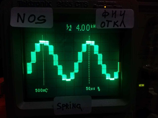
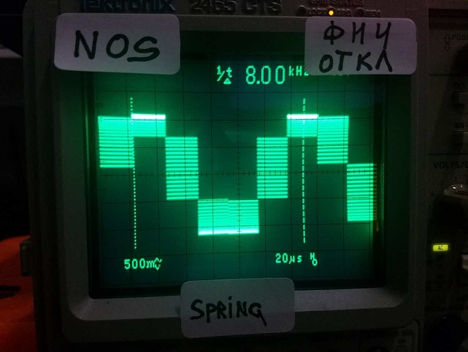
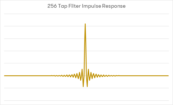
This diagram illustrates the output of the Modulator within the Ring DAC, modulating incoming digital audio signals to a 5-bit high rate format ready for conversion to analogue.
The next post will begin to discuss filtering in DACs.
What is a PWM DAC?Wow. It looks much closer to a multi bit PWM than an r2r at this point. A feedback loop would make it close to a delta Sigma. Im curious what classification this will fall into in the realm of r2r, delta Sigma and pwm dacs.
Does the DAC “know” which components are falling out of spec as it occurs, and compensate accordingly? Or is it just always running the same pattern, and over time the pattern proves useful in ameliorating the errors that slowly start to crop up?.
The nature of exactly how the Ring DAC decides which current sources need to be turned on or off at any given point to generate the correct signal is dictated by a highly sophisticated set of rules defined in the dCS Mapper. While it may appear to be random, it is the culmination of three decades of continuous work, resulting in a carefully calculated set of patterns used to minimise noise, distortion and crosstalk while primarily keeping the highest degree of linearity by averaging out the contribution of components that fall out of specification over time.
Feedback loop is in a 5-bit modulator (carefully hiding important details). It is a place where PCM data (bit-depth not shown) is converted to the DSD and then to the 5-bit multistream DSD64/128 (or both at once in one step). Mapper does an additional noise shaping (in addition what was done during oversampling). Noise shaping is a critical part of this type of decoder. Please don't confuse it with PCM decoding. It is a multistream DSD decoder as seen in all DS DAC chips today. This marketing 'tutorial' is trying to compare it to ladder PCM DACs, it is completely out of content.Wow. It looks much closer to a multi bit PWM than an r2r at this point. A feedback loop would make it close to a delta Sigma. Im curious what classification this will fall into in the realm of r2r, delta Sigma and pwm dacs.
I believe the randomization might be to decorrelate noise from audio signal. I don't know about all other dacs but ess has something very customized too (of course confidential). -120db distortions are with respect to sine waves or multitone sines (but sines at the end of the day), who knows how it'll vary with actual music/random signal given the fact that all of these conversions are primarily "algorithms" and there can be corners where they'll fail. Also how the spectrum of noise will vary, and how it relates to the listening experience. This is just my opinion/guess.Feedback loop is in a 5-bit modulator (carefully hiding important details). It is a place where PCM data (bit-depth not shown) is converted to the DSD and then to the 5-bit multistream DSD64/128 (or both at once in one step). Mapper does an additional noise shaping (in addition what was done during oversampling). Noise shaping is a critical part of this type of decoder. Please don't confuse it with PCM decoding. It is a multistream DSD decoder as seen in all DS DAC chips today. This marketing 'tutorial' is trying to compare it to ladder PCM DACs, it is completely out of content.
When I was evaluating dCS DAC many years ago, it was an innovative design, as most of CD-players were still bitstream. Much better than Sony bitstream chips, but it did sound like Delta-Sigma missing most of reverbations on a decay and harmonics were not true, but simplified leading to the same occasional artifacts. It subsequently lost to the very inexpensive CD player based on Burr-Brown PCM63. These days all modern Delta-Sigma DACs also use the same type of 5 or 6-bits converter, details are not published, it could be a concept borrowed from dCS (or in reverse).
The only difference from the current Delta-Sigma implementation is a randomisation of the output from this 5-bits-wide DSD data stream. Question is, why there is any need for randomisation while current DS chips easily achieve -120dB distortions. This is where 20-year old marketting (still in force as you see) fails, but it didn't change while a world made already number of steps forward since then. I would like to see a scientific paper giving justification for a complication of a design. Randomize -120dB distortions? .LOL.
You are absolutely right, all concern is about dynamic response. A dasboard FFT SINAD graph is an averaged result over thousands samples. This is the only way we can measure -120dB distortions. A lab equipment is not a Gods tool, it is subject to the same physical contrains. It is despite of a popular belief that measurements are objective and our hearing subjective. Not a case. Objective means presenting facts. When these facts present only an averaged result of DSP processing over thousand samples, it is just a small portion of a device characteristics, not a full picture of facts. It is just a digression.I believe the randomization might be to decorrelate noise from audio signal. I don't know about all other dacs but ess has something very customized too (of course confidential). -120db distortions are with respect to sine waves or multitone sines (but sines at the end of the day), who knows how it'll vary with actual music/random signal given the fact that all of these conversions are primarily "algorithms" and there can be corners where they'll fail. Also how the spectrum of noise will vary, and how it relates to the listening experience. This is just my opinion/guess.
I'll be interested to learn more about DCS answer. For the most part it does look closer to a delta Sigma than an r2r though.
Not sure what you are trying to say. Who is trying to avoid conventional design? They tried it 20 years ago when a product was innovative, but to expensive to become dominant on the market. A time is passing, nothing is changed and a world has advanced the same Delta-Sigma technology to a level, they are unable to convince customers to spend megabucks on their equipment when the same measured performance can be achieved on a $9 dongle. In other words, they dropped a ball somewhere between 0 and 20 years and now it is over.I would not want to speculate what algorithm ESS or DCS is using unless they themselves confirm it (or we could confirm it by analysis over real world signals, which imo wouldn't be a trivial task).
Regarding decorrelating noise from signal, if you happen to analyse a lot of music and generate a model/estimation, you could likely design a predictive logic that optimally works for such scenarios. And of course, any algorithm will have corner cases that will slip out, not much we could do about it. The end result is pretty much for the ears to judge with the music each person enjoys.
There's also this whole aspect of matching things with intrinsic behavior of the transistors/pcb/logic used. There may be hidden "compensations" we may not be aware of.
Point is, the whole process for both analog design and the dsp/algorithm for is an open playground and there can be so much variations. I wouldn't be looking to conclude all these dacs are the same just because they avoid a general conventional design for issues well known, as the possible other alternatives are likely infinite.