I'm going to write this up again for the benefit of those reading.
The graph which
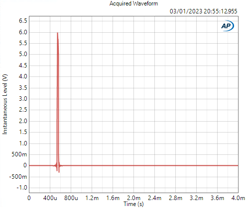
@sajunky is referring to is this one:
This is from John Atkinson's measurements of the May which can be found here:
https://www.stereophile.com/content/holoaudio-may-level-3-da-processor-measurements
Sajunky is asserting that what is being shown here is evidence of DSP because there is ringing visible on the graph, and a true NOS impulse should not have any ringing (it should be a square).
John Atkinson quite clearly states just before this graph:
"Ignore the very small amount of symmetrical ringing before and after the single full-scale sample, which is due to the antialiasing filter of Audio Precision's A/D converter operating at a sample rate of 200kHz"
Which is exactly what is happening here. Though Sajunky has chosen to ignore this and is using it as evidence of some sort of measurement cheat.
We can show this behaviour with some other devices quite easily, let's use a different brand and product just to be sure.
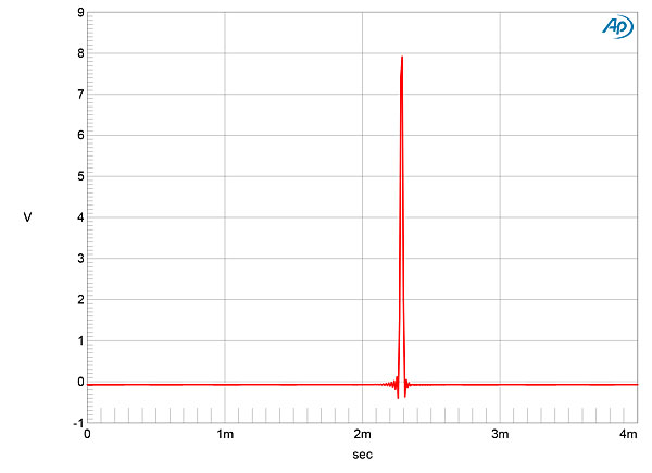
Here's the NOS impulse response of the Schiit Bifrost 2/64 recorded on the same analyzer with the same sample rate config that John Atkinson used:

Seems familiar eh?
Let's zoom in a bit (same measurement, just zoomes on the X axis)

Clear ringing! So it can't be NOS right?
Well, no, as John Atkinson stated, this is simply because the ADC is running at 200khz. A true square wave has an infinite bandwidth (in practice it's limited by the slew rate of the device), and so we aren't running the ADC fast enough to capture most of the signal.
Let's run it again, exactly the same, but this time run the ADC at 2.5Mhz to capture a higher bandwidth:

Lots less ringing!
So does this mean the DAC is ringing less?
No, the DAC is performing exactly the same. It's just that we're now capturing more of the signal.
The remaining 'ringing' seen on this particular impulse is then just because of impedance matching usually and is why in RF systems cables with characteristic impedances of 50 Ohms are used.
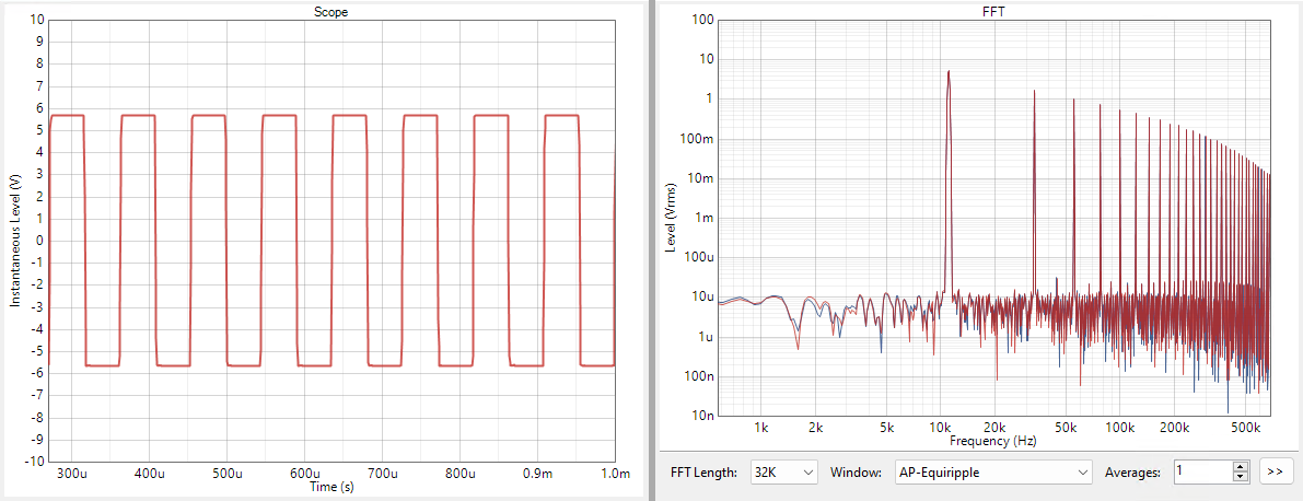
We can also repeat this very same behaviour with the analyzer's own square wave generator.
Here's an 11.025khz square wave for example:

No ringing, great! What if we measure this but with the ADC sampling rate reduced from 2.5Mhz to 200khz like with the earlier impulse response tests?

Ringing galore! Not because the signal ACTUALLY has any ringing on it (it doesn't), but because the ADC isn't sampling fast enough to capture the full signal. You cannot show a square wave if you have a limited bandwidth.
If we reduce the ADC sample rate to say 44.1khz, it now looks like this:

Looks like a sine wave now, not because it's actually a sine wave, but simply because we don't have enough bandwidth to capture above 22.05khz. And because even the first harmonic gets cut out by the filter, what we are left with is what LOOKS like a single sine.
Capturing (almost) the full bandwidth, over 1Mhz, we see a very square looking result:

Reduce your sample rate to ~200khz and therefore your capture bandwidth to 100khz, and you cut off most of the higher frequency components, meaning you cannot fully describe the square wave and are left with just the lower frequency components, which shows as ringing:

Cut it down further, to a 44.1khz ADC sample rate, and now you only have enough bandwidth to capture that first component. Everything else gets cut off. So it LOOKS like a sine on your display even though it's actually a square wave.

The ringing shown on the May measurement from JA is as JA himself said, simply because of the ADC being ran at a low-ish sample rate. When sampled higher, it does not ring. Nor is there any evidence of any unusual high frequency content or 'ultrasonic scrambling'.
He didn't say this because it DOES conform to the expected frequency response for sample & hold operation......