ClieOS's Random DIY Build Thread - [Updated: Oct.1st, 23] - Sony E282 Reproduction Shell Kit Build
Mar 16, 2021 at 6:36 AM Post #76 of 168
It has been almost 2 year ago that I challenged myself to fit a planar magnetic transducer into an earbud shell. The result, while good, can only be considered as 75% successful because of fit and sound. After all these time, I thought it is time to give it another go - with the same $120 planar magnetic transducer sourced from Aliexpress, but with a more ear-friendly shell - a MX500 type shell to be exact.

Parts Requirement:
1) 14.2mm planar magnetic driver x2
2) Transparent MX500 shell
3) Small rotary tool, i,e,. Dremel and small and small sanding bits
4) Normal soldering supply
5) Glue. In this case, the E8000, UV cured glue as well as thin 3M double sided tape.

PE2-01.JPG

PE2-02.JPG

As you can see, the 14.2mm transducer can fit into the front plate of the MX500 shell (*typically housing 15.6mm transducer) without any issue, but the back chamber will required heavy modification. Basically, all the side vents of the back chamber need to be sealed off with UV glue, then all the extra bit of plastic surrounding the back vents need to be sanded off until the planar magnetic transducer can fit completely inside with the front plate closed. While difficult, it is not impossible - though do be careful not to over-sand and penetrate the wall of the shell.

PE2-03.JPG

Lastly, the back vent of the shell is opened up (*many MX500 shell has a vent structure in the back but it is actually fully closed) to replaced the closed side vent. MMCX socket is fitted and soldered to the transducer. The transducer's side is fitted with double-sided tape to secured it into the back chamber, then the front plated is glued to the shell with E8000. Before the transducer is sealed in, the paper filter on the back of the transducer is moved to the front of the transducer to act as dampening filter / tuning.

Afterthought: As it stands, I'll call this a 90% success. First, fit has been dramatically improved from the wooden shell I used before. The new version required less critical fit to get a good sound out - which means I can use it more like a regular MX500 style earbuds which looser fit doesn't affecting SQ. Secondly, SQ has also improved as the new tuning has a more forgiving and relaxing sound than the old tuning. On its own, It is still a bit on the thin and bright side of presentation. With a bit of bass boost using EQ however, it sound rather balanced and neutral - definitely not something for bass-head, but otherwise a second to top-tier contender. The reason I called this a 90% success is because it does need the bass EQ to sound great, and I felt that I have pushed this particular transducer to its limit as far as an earbuds' transducer goes. To really address its weakness in bass, it will either be re-tuned as a driver or have a dedicated 2nd dynamic bass driver for a hybrid configuration.


----------------------


I found this particular unfinished old Aiwa earbud on Taobao - as far as I can tell, the driver is supposed to be used as mono headset, possibly as an accessory for portable radio and such. Since it is meant to be used as mono headset, there is no left / right side - so the easy part is just buy two of them and re-cable them for a stereo earbuds setup, but I take it one step further and re-terminate them into MMCX.

Parts Requirement:
1) Old Aiwa driver x2
2) Small rotary tool, i,e,. Dremel and small sanding bits
3) Thin MMCX socket x2, plus a bit of wires (Estron wires in my case)
4) Normal soldering supply
5) Heat gun

MA1-01.JPG

MA1-02.JPG

The front plate is glued fairly tight to the main chamber, but a bit of gentle warming from a heat gun will loosen it up. The housing is on the smaller size of thing so the cable exit needs to be widen up with a small rotary drill / sanding it order for it to fit a *small* MMCX socket. The tiny piece of foam on the vent is close to perish, so I replace them as well, using nozzle filter that normally meant for IEM. Without any filter / foam, the earbud will sounds to mid-centric. It can be tuned to a very neutral'ish sound by fully sealing the vent, though I opted for something closer to the original warmish tuning. The rest is pretty easy - just solder the MMCX socket to the driver, then glue them back together

MA1-03.JPG

MA1-04.JPG

Afterthought: I have never listened to any of those legendary old Aiwa earbuds before, so I have no idea how this particular pair compared them. But for the $20 or so I spent for parts cost, I reckon this pair of Aiwa doesn't sound too bad, though I won't go rushing out to recommend it to everyone either. One problem I did run into when I re-terminating the earbuds is that first two drivers I used have an slightly non-matching mid-range that I only found out after MMCX conversion. So I ended up re-terminating one more driver to create a matching pair (which means I have one extra driver wasted). As this was originally used as mono headset, matching is really a non-issue. But for converting to stereo setup, matching is a must and therefore you should get extra drivers as spare just in case of you ever want to do the same re-termination.

That's very impressive what you did there! Honestly! Keep it up :)
 
iFi audio Stay updated on iFi audio at their sponsor profile on Head-Fi.
 
https://twitter.com/ifiaudio https://www.instagram.com/ifiaudio/ https://ifi-audio.com/ https://www.youtube.com/@iFiaudiochannel comms@ifi-audio.com
Mar 18, 2021 at 5:46 AM Post #80 of 168
I thought of the idea when I saw it ,but glad to see someone doing it . I bet we can do est as well

Considering how regular planars sound like, if planar earbuds turn into a commercial product one day, I'll be the first one to try it out.
 
iFi audio Stay updated on iFi audio at their sponsor profile on Head-Fi.
 
https://twitter.com/ifiaudio https://www.instagram.com/ifiaudio/ https://ifi-audio.com/ https://www.youtube.com/@iFiaudiochannel comms@ifi-audio.com
Apr 15, 2021 at 10:07 PM Post #81 of 168
This is basically another take of the previous iFi xDSD's OTG cable build - instead of Type C to (female) USB-A however, this is a Type-C-to-Type-C OTG cable intended for the ever more popular Type-C audio adapter for smartphone.

Tools and parts needed:
1) Two Type-C OTG connector *
2) Short length of 4 cores ribbon cable
3) Basic modding / soldering supply.

* Note that not all Type-C connector out there support OTG function. You need to get the one specifically mentioned to support OTG. Also, you can use one OTG connector and one non-OTG connector to make an one-way cable, but here I choose to make it two-way. Last but not least - These Type-C connector should be 4 pins, meant for USB 2.0 compatibility.

CC1.JPG


Actual modding is pretty simple, just solder the connector together with the ribbon cable (V to V, D+ to D+, D- to D-, G to G)


CC2.JPG


How much cable length you want depends largely on the distance you want to position the audio adapter to your source. I'll recommend just make it slightly longer than the minimum.


CC3.JPG


The outer case is cut short in the middle to make them as minimalistic as possible, then glued together with super glue and B7000 (*headphone glue, mostly for filling in the cavity between the outer case and the Type-C connector). Note that the cable will be the weakest part of the assembly so care must be taken in use, i.e. not to pull on the cable when removing the OTG cable. This cable is meant to be used with the Type-C adapter semi-permanently double-taped to the back of the source, so flexibility isn't critical.

CC4.JPG
 
Last edited:
Apr 17, 2021 at 6:46 PM Post #82 of 168
This is basically another take of the previous iFi xDSD's OTG cable build - instead of Type C to (female) USB-A however, this is a Type-C-to-Type-C OTG cable intended for the ever more popular Type-C audio adapter for smartphone.

It looks fabulous! :beerchug:
 
iFi audio Stay updated on iFi audio at their sponsor profile on Head-Fi.
 
https://twitter.com/ifiaudio https://www.instagram.com/ifiaudio/ https://ifi-audio.com/ https://www.youtube.com/@iFiaudiochannel comms@ifi-audio.com
Jul 14, 2021 at 12:06 PM Post #83 of 168
First, I have been enjoying MoonDrop's Stardust (otherwise known as SSR) for awhile now. Secondly, I am a big fan of Etymotic ER4S and I am a big fan of TWS IEM, but ER4S is not exactly TWS-able even with an TWS adapter due to its long barrel shape. Stardust kinda fill in that gap for me to use with TWS adapter as it has a somewhat neutral'ish sound and the right shape, but it is not really Etymotic flat per se. So the idea of transforming a Starduct to ER4S via a driver-swap has been in my mind for awhile - that is, taking the dynamic driver out and putting a Knowles ED29689 (*same driver in ER4S) in while trying to getting it to sound as close to ER4S as possible. I call this new IEM the Stardust Memory (SDM)

Tools and parts needed:
1) Moondrop Stardust
2) Knowles ED-29689 balanced armature driver x 2 (*matched pair, if you can find them that way)
3) Balanced armature adapters x 2 (*found on TB)
4) 100 ohm Vashay CMF50 resistor x 2
5) Estron Linum internal wires
6) Knowles green filter x 2
7) UV and B-7000 headphone glue
8) Basic modding / soldering supply.
9) Heat gun
10) Hex tool Torx T6

SDM-01.jpg


SDM-02.jpg


The first step is to dissemble the Stardust. Remove the screw with Torx T6 hex tool. The shell is glued quite tightly so a bit of heating to loosen up the glue with a heat gun will helps a lot. Pry tool helps as well. There are some white foam glue surrounding the driver - it can be removed easily with any shape tool. Note the driver has a beryllium (*poison in certain form) coated diaphragm, so please handle with care. Once the white foam is removed, the 0.78mm socket (also glued down) can be pried up. Then by pulling the 0.78mm socket out with the wires still connected to the driver, the whole assembly can be removed from the housing. Once the whole assembly is out, desolder the wires from the 0.78mm socket. Clean up the housing and remove the filter from nozzle.

SDM-03.jpg


Next step is to prep the BA adapter by shorten it to the nozzle length is around 9.3mm (similar to that of ER4S nozzle) The base of the adapter (*red arrow) needed to be files down in order for it to fit securely inside the housing as well. Note that the adapter's nozzle will be acentric to the housing's nozzle, but a bit of heat from the heat glue and a little bending will fix the issue. Then the adapter is secured into the housing nozzle with a combination of UV and B-7000 headphone glue.

SDM-04.jpg


SDM-05.jpg


SDM-06.JPG


The side opening on the housing's nozzle can be sealed off with some UV glue. The is a dust filter on the inside that needed to be taken out first.

SDM-07.jpg


Now the wiring as well as the resistor can be soldered in. Please note the positive / hot and negative / ground terminals on the 0.78mm socket - the (+) trinomial is facing to the back of the head while the (-) terminal is facing forward when the housing is in the ear. Also note that on the picture below, I solder the 100ohm Vishay CMF50 100ohm resistor to the + terminal of the 0.78mm socket as well as to the ED-29689 positive terminal. This will end up getting a sound that has a reversed polarity. To get the correct polarity, the resistor should connect to ED-29689's negative terminal.

SDM-08.jpg


Once both sides have been soldered, you can fit the Knowle4s green filter into the nozzle. They should fit right in without any modification. Now the face plate as well as the screw can go back in. Also, don't forget to pout a tiny bit of glue underneath the 0.78mm socket to secure it in place

SDM-09.jpg


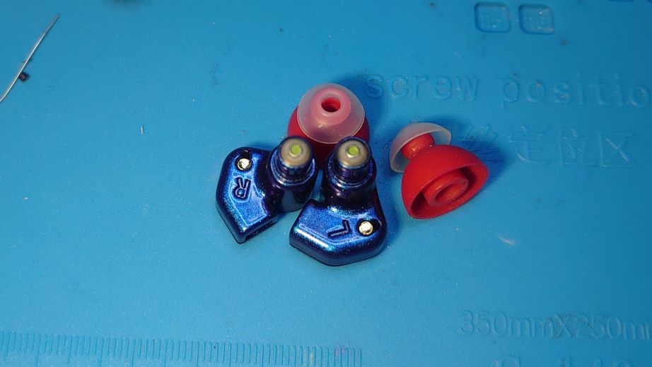
If done correctly, the Stardust Memory should look almost identical to the original Stardust and can't be tell apart without looking at the nozzle.

SDM-10.jpg


SDM-11.jpg


SDM.png

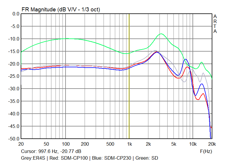
SD = Stardust (measured with CP100)
SDM = Stardust Memory
CP100 = Spinfit CP100 eartips
CP230 = Spinfit CP230 eartips

Afterthought: as far replicating ER4S into a Stardust housing, you can see on the measured FR curve above that it is not really a complete success, notably on the upper mid-range to (especially) treble. But as far as creating a fairly flat and clean sounding IEM to be used with TWS adapter, it is definitely well worth the effort. Due to the shape of the nozzle, different eartips also seems to influence the upper mid to treble response by a lot, so it will still need more experiment with different eartips for finetuning. But as far as wired usage, I like the Spinfit CP100 with SDM the most. With TWS adapter (*OE Audio WS-1 in this case) however, the CP230 seems to complement it the best. Also, a little bit of EQ to compensate for the treble can push it closer to that of ER4S. On hindsight, perhaps 75ohm or 50ohm resistor can be used for a slightly warmer sound. For now, I am happy for what it is.
 
Last edited:
Jul 14, 2021 at 1:11 PM Post #85 of 168
Amazing work, man. Can you suggest some good resistors for DD?
Vishay CMF50, mentioned above, is a pretty good choice. If you prefer something more in regular size (*CMF50 is smaller in general), CMF55 is a well received choice for audio use as well. If you want something in the SMD range, thin firm is usually preferred.
 
Jul 14, 2021 at 1:22 PM Post #86 of 168
Vishay CMF50, mentioned above, is a pretty good choice. If you prefer something more in regular size (*CMF50 is smaller in general), CMF55 is a well received choice for audio use as well. If you want something in the SMD range, thin firm is usually preferred.
Thanks. I will check them out. I know that ShoonTH use resistors for their buds and I don't see any proper example how to use it with DD.
 
Jul 14, 2021 at 4:36 PM Post #87 of 168
First, I have been enjoying MoonDrop's Stardust (otherwise known as SSR) for awhile now. Secondly, I am a big fan of Etymotic ER4S and I am a big fan of TWS IEM, but ER4S is not exactly TWS-able even with an TWS adapter due to its long barrel shape. Stardust kinda fill in that gap for me to use with TWS adapter as it has a somewhat neutral'ish sound and the right shape, but it is not really Etymotic flat per se. So the idea of transforming a Starduct to ER4S via a driver-swap has been in my mind for awhile - that is, taking the dynamic driver out and putting a Knowles ED29689 (*same driver in ER4S) in while trying to getting it to sound as close to ER4S as possible. I call this new IEM the Stardust Memory (SDM)

Tools and parts needed:
1) Moondrop Stardust
2) Knowles ED-29689 balanced armature driver x 2 (*matched pair, if you can find them that way)
3) Balanced armature adapters x 2 (*found on TB)
4) 100 ohm Vashay CMF50 resistor x 2
5) Estron Linum internal wires
6) Knowles green filter x 2
7) UV and B-7000 headphone glue
8) Basic modding / soldering supply.
9) Heat gun
10) Hex tool Torx T6

SDM-01.jpg


SDM-02.jpg

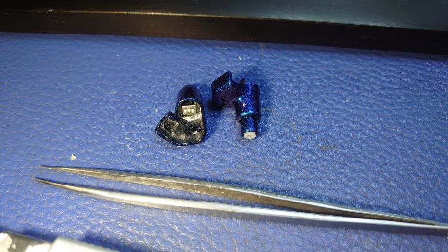
The first step is to dissemble the Stardust. Remove the screw with Torx T6 hex tool. The shell is glued quite tightly so a bit of heating to loosen up the glue with a heat gun will helps a lot. Pry tool helps as well. There are some white foam glue surrounding the driver - it can be removed easily with any shape tool. Note the driver has a beryllium (*poison in certain form) coated diaphragm, so please handle with care. Once the white foam is removed, the 0.78mm socket (also glued down) can be pried up. Then by pulling the 0.78mm socket out with the wires still connected to the driver, the whole assembly can be removed from the housing. Once the whole assembly is out, desolder the wires from the 0.78mm socket. Clean up the housing and remove the filter from nozzle.

SDM-03.jpg

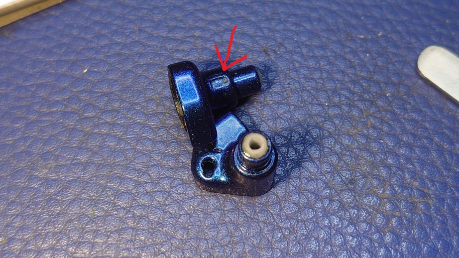
Next step is to prep the BA adapter by shorten it to the nozzle length is around 9.3mm (similar to that of ER4S nozzle) The base of the adapter (*red arrow) needed to be files down in order for it to fit securely inside the housing as well. Note that the adapter's nozzle will be acentric to the housing's nozzle, but a bit of heat from the heat glue and a little bending will fix the issue. Then the adapter is secured into the housing nozzle with a combination of UV and B-7000 headphone glue.

SDM-04.jpg

SDM-05.jpg

SDM-06.JPG

The side opening on the housing's nozzle can be sealed off with some UV glue. The is a dust filter on the inside that needed to be taken out first.

SDM-07.jpg

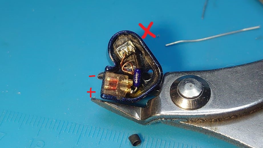
Now the wiring as well as the resistor can be soldered in. Please note the positive / hot and negative / ground terminals on the 0.78mm socket - the (+) trinomial is facing to the back of the head while the (-) terminal is facing forward when the housing is in the ear. Also note that on the picture below, I solder the 100ohm Vishay CMF50 100ohm resistor to the + terminal of the 0.78mm socket as well as to the ED-29689 positive terminal. This will end up getting a sound that has a reversed polarity. To get the correct polarity, the resistor should connect to ED-29689's negative terminal.

SDM-08.jpg

Once both sides have been soldered, you can fit the Knowle4s green filter into the nozzle. They should fit right in without any modification. Now the face plate as well as the screw can go back in. Also, don't forget to pout a tiny bit of glue underneath the 0.78mm socket to secure it in place

SDM-09.jpg

If done correctly, the Stardust Memory should look almost identical to the original Stardust and can't be tell apart without looking at the nozzle.

SDM-10.jpg

SDM-11.jpg

SDM.png
SD = Stardust (measured with CP100)
SDM = Stardust Memory
CP100 = Spinfit CP100 eartips
CP230 = Spinfit CP230 eartips

Afterthought: as far replicating ER4S into a Stardust housing, you can see on the measured FR curve above that it is not really a complete success, notably on the upper mid-range to (especially) treble. But as far as creating a fairly flat and clean sounding IEM to be used with TWS adapter, it is definitely well worth the effort. Due to the shape of the nozzle, different eartips also seems to influence the upper mid to treble response by a lot, so it will still need more experiment with different eartips for finetuning. But as far as wired usage, I like the Spinfit CP100 with SDM the most. With TWS adapter (*OE Audio WS-1 in this case) however, the CP230 seems to complement it the best. Also, a little bit of EQ to compensate for the treble can push it closer to that of ER4S. On hindsight, perhaps 75ohm or 50ohm resistor can be used for a slightly warmer sound. For now, I am happy for what it is.

Lovely work, keep 'em coming :beerchug:
 
iFi audio Stay updated on iFi audio at their sponsor profile on Head-Fi.
 
https://twitter.com/ifiaudio https://www.instagram.com/ifiaudio/ https://ifi-audio.com/ https://www.youtube.com/@iFiaudiochannel comms@ifi-audio.com
Dec 3, 2021 at 2:52 AM Post #88 of 168
As far as I know there has not been any attempt to build an earbud such as this - one with planar magnetic transducer. I know we have seen some IEM with planar drivers (among others types) but earbud is simply too out of fashion for anything but a normal dynamic driver, This particular pair of planar come from the same OEM factory that recently makes the **** MT100 and Toneking BL1. Some of these bare drivers was sold on Taobao as well as Aliexpress, which is where I got mine. You don't really find planar driver of this size (or most of any size really) and thus the rarity costs money, almost $120 for a pair to be exact. The diameter of the driver is 14.2mm, which seems to be fairly normal when compared to dynamic driver. But given it is a planar driver, it is actually far larger than similar dynamic transducer of the same diameter. To find a suitable housing has became the first major obstacle. I have managed to source a rather large wooden housing that is meant for 15mm driver.

Parts Requirement:
1) 14.2mm planar magnetic driver x2
2) Large wooden housing x2
3) Small rotary tool, i,e,. Dremel and small wood working bits
4) Normal soldering supply
5) Glue. In this case, the E8000, UV cured glue as well as thin 3M double sided tape.

PE001.JPG

You can tell from the picture above that the planar driver has a pancake / sandwich structure (silver for the front and blue for the back. front grill is covered by mesh while back vent is covered by paper, there are also 4 small holes on the size that allows air to move around - more on these small holes later). The wooden housing already has mmmcx socket permanently attched and a small vent hole can is just next to the mmcx socket.

PE002.JPG
Because of the rather flat structure of the planar driver, it won't fit into the wooden housing . You can see the unmoded housing on the right and the moded housing on the left - some wood has to be removed to make room for the driver as well as the screws that stick out of the driver. This is where the oversized housing comes in handy as it still has plenty of 'meat' that you can trim away without causing any problem.

PE003.JPG

A great deal of experiement had went into the tuning to get the 'right sound' - remember that these driver are tuned for IEM housing, so putting them into earbud housing unavoidably created a long list of problems - mainly the earbuds just do not sound anywhere decent. After numerous trial and error, I figure out the driver needs two things: First, a completely sealed back chamber and 2nd, tons of acoustic impedance on the front.

Without the sealed back chamber, bass is almost completely gone (even with just a tiny hole). So the small vent next to the mmcx socket is sealed off by UV glued, a small piece of foam was placed n the back chamber in hope to reduce resonance. Then the 4 small hole that connect the front to the back is sealed off as well (you can see the 4 tiny heavy Y4 filters next to the white paper filter on the driver's back vent)

To increase acoustic impedance, a large piece of foam (*same kind on foam pad) is used to cover the whole front grill of the driver. The UV glue is used to sealed off all the vent holes on the front face plate of the wooden housing except for the center hole. A heavy filter (the type normally used on IEM's nozzle) was glued over the center hole to further increase the acoustic impedance.

Lastly, two layers of thin 3M double sided tape is cut and glue to the side of the planar driver, then affixed into the wooden face plate. I am avoiding liquid glue here because there might be a risk of them running in between the sandwich of the driver. The driver is also slightly smaller than the housing's inner diameter, so a little bit of tape helps to fill in the gap. Once affixed, a little bit of E8000 is used to fill in to the gap to make sure there won't be any air leak on the tape (*which I won't need to be worry of them running into the driver since the tape already has the edge mostly sealed up. Once the driver is sealed up, the wooden housing is glued together with the E8000.

PE004.JPG

Here is the finished earbuds, the first of its kind and I named it 'PE1', as in Planar Earbud One.

PE005.JPG

Here is a size comparison with MX500 style housing - Yes, it is not small by any measure.

PE006.JPG

The completed view

Afterthought: I'll call this project 75% successful. First of, the drives are tuned with IEM housing in mind and regardless of how much I try to compensate, it is simply not in its element. I know this because whenever I pressed the finished earbuds to my ears very tightly, the SQ immediately improves, and not by small margin. For now, even after all the things I have done to increase the acoustic impedance, the earbud still sound on the thin and bright side. I need to use double foam with a very controlled fit to order to achieve a seal good enough for a decent sound. Once the seal is loosen even sightly, SQ suffers. Beyond the fact that SQ is not optimized, the rest of the build is actually all good. I know early on that this will not be an easy build but the actual process is simpler than I have imagined. Most of the time really was spent on tuning for a decent sound. I felt I have done all I can with these planar drivers - as a proof of concept, putting planar into earbuds is definitely more than possible. In fact, it can be extremely good sounding if tuned right - by judging from all the tuning work I have done. We just need the right planar driver for the job.

PE-1t.png
Mod, measure, repeat - all to find the right sound.

PE-1 FR.png
This is what the final earbud sounds like. Almost a 2nd tier when the fit is right.
If you can wear an artificial ear model on the measuring instrument, the curve will be much correct.
 

Attachments

  • screenshot-20211203-154941.png
    screenshot-20211203-154941.png
    95.1 KB · Views: 0
FiiO Stay updated on FiiO at their sponsor profile on Head-Fi.
 
https://www.facebook.com/FiiOAUDIO https://twitter.com/FiiO_official https://www.instagram.com/fiioofficial/ https://www.fiio.com support@fiio.com
Dec 3, 2021 at 5:13 PM Post #89 of 168
Next step is to prep the BA adapter by shorten it to the nozzle length is around 9.3mm (similar to that of ER4S nozzle)
I'm late but curious.
Did you test the impact of the nozzle length on FR with the tips sitting at the same place on the coupler?
As this shell would clearly not go as deep as an er4, the ear canal gain would be different(not that it matters too much given that we all have different ear canal length). something we seem to see, not too clearly at the first resonance freq, but more obviously at the second around 8-10kHz.
I don't know if the nozzle acts as a second resonator(first to me being the ear canal) for tuning, or if it somehow adds up with the ear canal as one tube(probably not)? In which case a shorter nozzle tube might push the bump back closer to 10kHz?
 
Dec 3, 2021 at 7:34 PM Post #90 of 168
I'm late but curious.
Did you test the impact of the nozzle length on FR with the tips sitting at the same place on the coupler?
As this shell would clearly not go as deep as an er4, the ear canal gain would be different(not that it matters too much given that we all have different ear canal length). something we seem to see, not too clearly at the first resonance freq, but more obviously at the second around 8-10kHz.
I don't know if the nozzle acts as a second resonator(first to me being the ear canal) for tuning, or if it somehow adds up with the ear canal as one tube(probably not)? In which case a shorter nozzle tube might push the bump back closer to 10kHz?

The reason of the nozzle length is to keep the distance between the filter / damper and the BA driver as close to the original as possible. Test by others had shown the distance is crucial to getting the right sound out of the BA. The other crucial factor is the eartips bore size / length and how deep it sits in the ear canal, which unfortunately can't be alter due to the the nature of the metal housing. The problem is the large diameter of the outer nozzle that change how the width of the eartips as well as how deep it can go into the ear. To remedy this to an extend, the best thing to do is to try different eartips design in order to get as close to the original as possible. But to be completely accurate is just imposibiel.
 

Users who are viewing this thread

Back
Top