Chameleon DAC listening and modifications
May 29, 2010 at 4:18 PM Post #991 of 1,158
Can you provide a link to pics of what the PSU PCB should look like?  I emailed TeraDak on the ebay vendor's version, and TeraDak said they shipped 2 versions of the Chameleon to vintage audio.  I'm thinking maybe one of those versions is the latest one?
 
Of course, I could just get TeraDak's $400 version, then buy some caps for the analog output myself.  How much would this route cost me?
 
May 31, 2010 at 9:27 AM Post #992 of 1,158
Hi all,
 
i was just wondering, since there's a few of us here are using the ultravox, anyone hard wire direct to the Chameleon's input board? i hard wired mine to the solder point of the female usb plug, but just thinking it would be much better to wire it directly to the board somewhere bypassing the trace on the PCB.
 
has any tried?
 
Jun 1, 2010 at 5:31 AM Post #993 of 1,158


Quote:
Hi all,
 
i was just wondering, since there's a few of us here are using the ultravox, anyone hard wire direct to the Chameleon's input board? i hard wired mine to the solder point of the female usb plug, but just thinking it would be much better to wire it directly to the board somewhere bypassing the trace on the PCB.
 
has any tried?

 
Should be doable. Have you got the schematic?
 
 
Jun 2, 2010 at 2:41 PM Post #994 of 1,158
Taiphan- yes just follow the traces over to the input board, the USB data input is marked D+ & D-. Use an ohm meter to make sure which one is which and then solder to the upper backside pins on the input board. The other two wires on the USB are power and ground, the power wire is a direct connection to the yellow LED light on the front, myself I would not hook it up. Not sure if you need to hook up the ground wire, hopefully not. Why don't you do a little experiment for everyone and disconnect the power ... then the ground ... from the output of the Ultravox and see if the USB still works. After that it's just a matter of filing out a larger USB hole, mounting the Ultravox internally and hard wiring the D+/D-. Keep us posted.
 
Here is a picture of the input board with light shining through it so you can see all the traces. You can easily see the D+/D- USB input traces to the Tenor USB chips. Next to them is a separate ground wire for the 3.3V regulator for the Tenor chip and the HC157. The HC157 provides the output switching of the I2S from either the Tenor or Wolfson chip to the reclock board and ultimately the DAC chips. Its this separate grounding trace that I suspect cause havoc with the Spdif input/I2s output and the reason the IFU mod works so well.


If you look careful I have removed the Pulse transformer exposing the ground traces underneath. I cut the trace and removed the pin under the number 5 effectively moving the entire ground plane for the Spdif input circuitry over to my source ... IFU mod.  (Primary on Pulse, 12Mhz clock, Wolfson Spdif receiver chip, 3.3v power regulator and 74H04 USB/Spdif logic chip). Tony and I have achieved excellent results by doing this but this will depend on how clean your source ground is. (Notice the secondary ground trace going down, it is still grounded to the same point on the main board.)
 
If you want to float "just" the Spdif input to the Pulse transformer, the original intention of the FIM (floating input mod) then this gets a bit more complex as the 75 ohm resistor to load the Spdif input is located on the back of the board. This is a "tiny" surface mount resistor and I had no luck moving it over to the secondary pad, which by the way Nugent says is the ideal location for the 75 ohm resistor. If you could get that done then a true FIM is easy; remove the 2 primary pins on the pulse transformer and bend it back away from the board, next solder the coax Spdif input wires directly to the primary leaving the board traces intact. There is a lot of controversy on how best to handle Spdif input, myself I always prefer the simplest and cleanest approach.
 
Here is a shot of the back side of board. The 75 ohm surface mount resistor is located under the b for bypass. If you are very careful you can move it over to the open secondary pad right next door. Another awesome solution would be to solder in a 75 ohm Z-foil resistor to this location or across the primary, your choice.


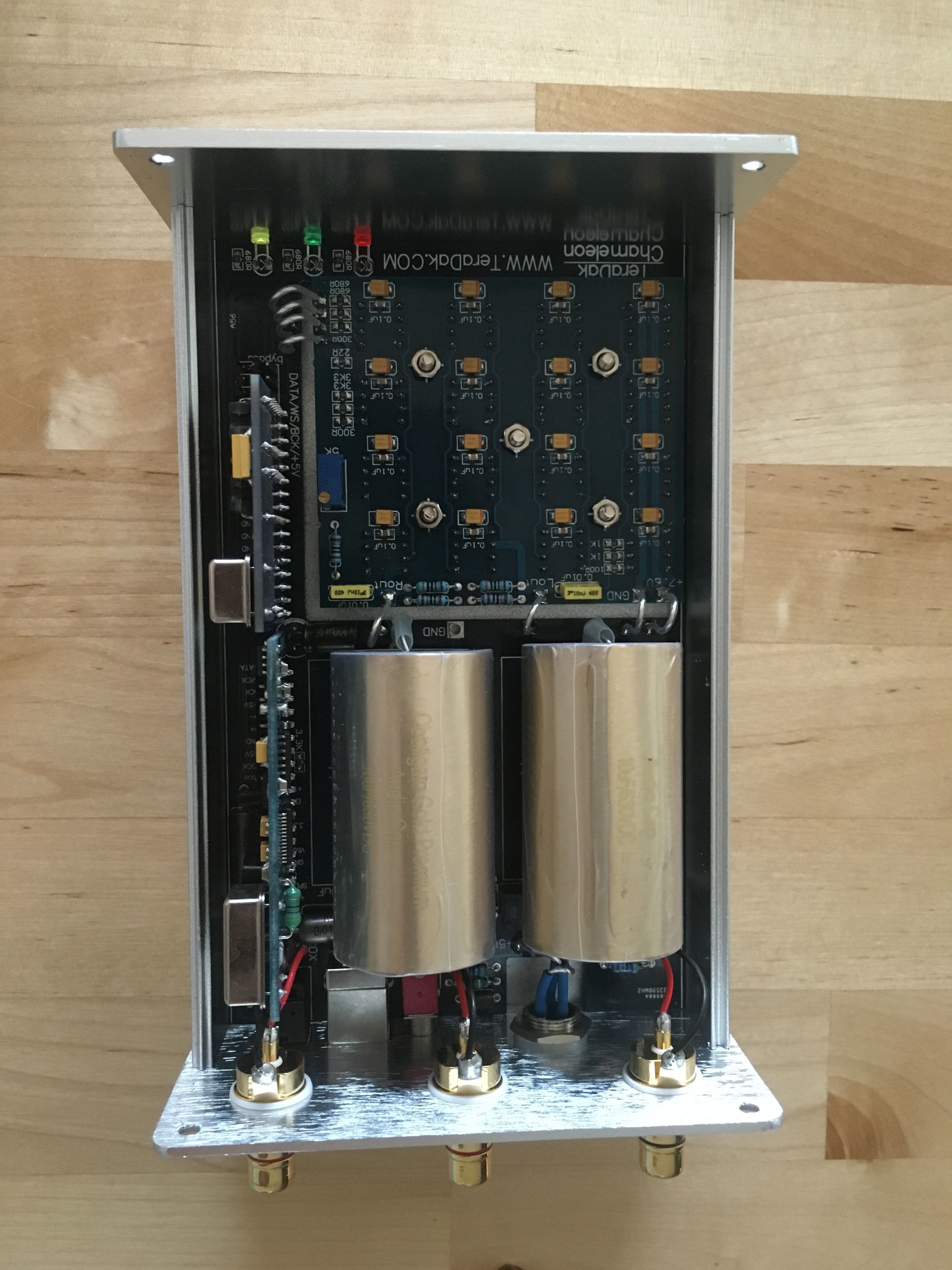
Here is a picture of the my friend Jay's Chameleon that I just got done installing the 47uf Blackgate FK's and .1uf Vishay Roderstein MKP-1837 film bypass caps. It was like a jigsaw puzzle getting them to fit in ... but they do fit! I started by wrapping the legs and soldering the film caps to the Blackgates. You will also want to remove both 10uf and .1uf factory installed surface mount caps before you solder down the Blackgates in the provided holes. The row of Blackgate's nearest the front do not have through holes so you must bend the Blackgate legs and solder to the pads where the 10uf caps were. (Leave the row behind this row open to provide easy access to solder these legs down first.)


In the past I used .01 MKP-1837 bypasses for the Blackgates, while they are easier to install the .1uf MKP's  proved to be superior sounding. This is yet another Steve Nugent tip, every little thing makes a difference at this stage of the game.
Thanks again, Steve!
 
The DAC above is stock except for the Blackgates and bypass caps, one could leave well enough alone and enjoy there Chameleon doing nothing else. This is the by far the biggest bang for the buck IMO. Everything else is just Gravy!!!
 
Jun 2, 2010 at 8:59 PM Post #995 of 1,158
 
You can't cut the ground of the USB - it will render the USB inoperable & may damage the USB receiver in the Tenor chip. Even though the USB signals are differential (ie.e no ground is needed) the ground seems to be used as a reference for USB signalling & commands.
 
I'm not sure what the implications of cutting the ground on pin 4 (not pin 5) is - this also provides the ground to the clock & bypass caps in other areas. To me it would seem like what you've done is introduce a large ground loop between the ground of whatever is connected through the SPDIF source & the Chameleon ground. What happens if you have nothing connected to SPDIF?
 
I agree though that the boards grounding is a bit of a mess - it could do with a single star ground or a ground plane.
 
Jun 3, 2010 at 4:38 AM Post #996 of 1,158

 
Quote:
 
In the past I used .01 MKP-1837 bypasses for the Blackgates, while they are easier to install the .1uf MKP's  proved to be superior sounding. This is yet another Steve Nugent tip, every little thing makes a difference at this stage of the game.
Thanks again, Steve!
 
The DAC above is stock except for the Blackgates and bypass caps, one could leave well enough alone and enjoy there Chameleon doing nothing else. This is the by far the biggest bang for the buck IMO. Everything else is just Gravy!!!

 
Bill, What differences did you experience when you changed from 0.01uF to 0,1uF MKP's? I might want to try it but it depends on the changes it gives as i'm quite satisfied now.
 
btw, I received my Paul Hynes power supplies & regulators yesterday. I will add the power supplies later but I couldn't wait replacing the LM1117 regs for the WM8805 and AD1895. :)


Jun 3, 2010 at 6:50 PM Post #997 of 1,158

 
Quote:
 
 
Bill, What differences did you experience when you changed from 0.01uF to 0,1uF MKP's? I might want to try it but it depends on the changes it gives as i'm quite satisfied now.
 
btw, I received my Paul Hynes power supplies & regulators yesterday. I will add the power supplies later but I couldn't wait replacing the LM1117 regs for the WM8805 and AD1895. :)


Rhodes - at the level of the game you play at I would say upgrading to .1uf caps will be well worth your effort. I have 3 Chameleon DAC's at my disposal, one with just BG's on the DAC chips, one with GB's & .01uf bypass, and one with BG's and .1uf bypasses. The sound is akin to adding larger, more powerful, and better quality amps to your system.  It really is surprising how different they all sound.
 
For those about to mod this is my list of the largest gains for money spent. (LGFMS)
 
#1 Adding .47uf Blackgate FK's with .1uf film bypass caps on each DAC chip.
 
#2 VSF Dueland or Jupiter flat stacked coupling caps. (Perhaps output Transformers but I have yet to try them)
 
#3 LifePo4 Battery supply for the 5VDC rail.
 
Let me elaborate on number 3. Look at the time and expense Rhodes went through to lower the jitter on the digital input circuitry to the DAC chips. He was clearly able to hear an improvement at each step along the way. A much simpler and lower cost alternative is to use the latest battery technology (LiFePo4) to power the 5 VDC rail on the Chameleon. While you will still be using all the same stock parts, logic dictates that reducing the ripple on the 5VDC rail will lower overall jitter/voltage distortions. I propose using a battery & charger for RC cars with a built in low voltage auto cut off for safety. We can lower the voltage to 5VDC using a simple inline resistor hopefully not needing a regulator. Perhaps recyling the Spdif switch to select from stock 5VDC supply or Battery 5 VDC.
 
I have yet to try this but I do believe this to be a worthwhile adventure. Game On!
 
 
Jun 4, 2010 at 4:35 AM Post #998 of 1,158
#1 Adding .47uf Blackgate FK's with .1uf film bypass caps on each DAC chip.
 
#2 VSF Dueland or Jupiter flat stacked coupling caps. (Perhaps output Transformers but I have yet to try them)
 
#3 LifePo4 Battery supply for the 5VDC rail.
 
Good solid core recommendations!
 
I may leave the .01uf film bypass in place and try another, smaller .1uf film for a triple bypass.
 
LifePo4.... I hope to try in the coming weeks, the downside is having to charge them at night, but, as you suspect Bill, everything else should be up up up!
 
Coupling caps, I am currently testing Russian Teflon FT-3 in this position, its to early to give a recomendation now, as its only 1 week break in. But they are putting up a very promising show so far, and that's up against the excellent Jupiter's! so for for anybody who might want to try Teflon coupling for a 10th of the usual price, I will report back later, but only when/if I am certain they are a real contender, unconsidered cap recommendations in this position can easily run amok, and distract from more considered and valuable experiences leading to frustration and confusion.
 
With all these mods scattered on the thread, and now the Chameleon is in production, I propose that we start an open, editable list, that orders mods by bang for buck and skill level based on our experiences. (For example number one has to be removing the filter caps). Must be remembered that in a sense we have 2 dacs here, USB and SPIDF. So the list will have to split at some point when covering input. But a reference point will make the mod options clearer and more easily accessible for new owners to try, and expand on.
 
Jun 4, 2010 at 8:49 AM Post #999 of 1,158
Yep I direct wired the d+/d- directly to the board. However you will need to wire the ground and + wire too, as this acts as a switch for the dac to select usb input, otherwise it will default to coax.


Quote:
Taiphan- yes just follow the traces over to the input board, the USB data input is marked D+ & D-. Use an ohm meter to make sure which one is which and then solder to the upper backside pins on the input board. The other two wires on the USB are power and ground, the power wire is a direct connection to the yellow LED light on the front, myself I would not hook it up. Not sure if you need to hook up the ground wire, hopefully not. Why don't you do a little experiment for everyone and disconnect the power ... then the ground ... from the output of the Ultravox and see if the USB still works. After that it's just a matter of filing out a larger USB hole, mounting the Ultravox internally and hard wiring the D+/D-. Keep us posted.
 
Here is a picture of the input board with light shining through it so you can see all the traces. You can easily see the D+/D- USB input traces to the Tenor USB chips. Next to them is a separate ground wire for the 3.3V regulator for the Tenor chip and the HC157. The HC157 provides the output switching of the I2S from either the Tenor or Wolfson chip to the reclock board and ultimately the DAC chips. Its this separate grounding trace that I suspect cause havoc with the Spdif input/I2s output and the reason the IFU mod works so well.


If you look careful I have removed the Pulse transformer exposing the ground traces underneath. I cut the trace and removed the pin under the number 5 effectively moving the entire ground plane for the Spdif input circuitry over to my source ... IFU mod.  (Primary on Pulse, 12Mhz clock, Wolfson Spdif receiver chip, 3.3v power regulator and 74H04 USB/Spdif logic chip). Tony and I have achieved excellent results by doing this but this will depend on how clean your source ground is. (Notice the secondary ground trace going down, it is still grounded to the same point on the main board.)


Jun 4, 2010 at 11:15 AM Post #1,000 of 1,158


Quote:
Rhodes - at the level of the game you play at I would say upgrading to .1uf caps will be well worth your effort. I have 3 Chameleon DAC's at my disposal, one with just BG's on the DAC chips, one with GB's & .01uf bypass, and one with BG's and .1uf bypasses. The sound is akin to adding larger, more powerful, and better quality amps to your system.  It really is surprising how different they all sound.


Hi Bill,
 
 Can you describe what kind of differences you experience between the 0,01 anf 0,1uF caps? I would expect increased dynamics and maybe better bass resolution.
 
Jun 4, 2010 at 1:40 PM Post #1,001 of 1,158
Very nice work Taipan, did you notice any improvments, any chance of a pic so others could give it a try?
 
Jun 4, 2010 at 3:16 PM Post #1,003 of 1,158
I'm still using the .01 vishay rhodes.
 
Jun 5, 2010 at 3:53 AM Post #1,005 of 1,158

 
Quote:
 
Hi Bill,
 
 Can you describe what kind of differences you experience between the 0,01 anf 0,1uF caps? I would expect increased dynamics and maybe better bass resolution.

Rhodes- yes better dynamics and resolution but more on a global level. I described it earlier as akin to adding a more powerful and better quality amp to your system. Which of coarse you are doing as every change to the 8 VDC rail for the DAC chips will change how the DAC sounds. After all ... the 16 DAC chips in the Chameleon are collectively our source amplifier.
 
Will you be powering the 8 VDC rail for the DAC chips with any of your new power supplies?
 
I have thinking about trying to power the entire DAC on the new LiFePo4 batteries. In the past I tried using lithium ion and lead acid batteries but just couldn't capture the dynamics. The LiFePo4 batteries on the other hand offer exponentially lower internal resistance, close to that of the best film caps. This should translate into much greater speed and dynamics and off coarse much lower noise. If we can get the batteries really close to the DAC chips we might not even need a Film Reservoir Mod (FRM).
 
As I said ... Game On!
 

Users who are viewing this thread

Back
Top