Cavalli EHHA Embedded Hybrid Headphone Amp
Apr 23, 2010 at 5:40 AM Post #1,456 of 1,823
1/2 watt will do for headphone duty.

We'll figure out the problem with the tube biasing. What's the voltage on either side of R3 and R4 with respect to SG? ANd voltage at pins 1 and 6 of the tube again with wrt SG.
 
Apr 23, 2010 at 6:20 PM Post #1,457 of 1,823
After spending 2 hours troubleshooting (under rated fuse
redface.gif
) I finally got my first EHHA board tested and it measures OK!
biggrin.gif

R3 1.513V, R4 1.475V (1.5V)
R10 1.494V, R14 1.444V (1.5V)
R15 0.888V, R17 0.795V (0.85V)
R16 0.564V, R18 0.674V, R26 0.535V, R29 0.644V (0.65V)
DC voltage at the output stays bellow 1mV.

I'm having trouble with cooling the mosfets though, the heat sinks that came with the kit are the equivalent of 11C/W heat sinks and the recommended ones are 2.6C/W heat sinks. In minutes the heat sinks get hot enough to burn my fingers, so I need to place this build on hold for now
frown.gif
 
Apr 23, 2010 at 6:48 PM Post #1,458 of 1,823
YOu probably have the bias point turned up waay too high. A mistkae i made too when i got my first EHHA going..had the mosfets burning nearly 450mA. Fortunately i had offboard heatsinks.

So assuming the output is towards you and the tube is on the other end of the board, turn R21 counter clockwise a few times while measuring the voltage across either R32 or R33. Keep your multimeter in the 2V range.

Turn the trimpot R21 counter clockwise till you read 0.22V or 220mV.
 
Apr 23, 2010 at 7:39 PM Post #1,459 of 1,823
Quote:

Originally Posted by sachu /img/forum/go_quote.gif
YOu probably have the bias point turned up waay too high. A mistkae i made too when i got my first EHHA going..had the mosfets burning nearly 450mA. Fortunately i had offboard heatsinks.

So assuming the output is towards you and the tube is on the other end of the board, turn R21 counter clockwise a few times while measuring the voltage across either R32 or R33. Keep your multimeter in the 2V range.

Turn the trimpot R21 counter clockwise till you read 0.22V or 220mV.


R32 and R33 are at 270mV at start up. After a few minutes they are bellow 220mV, so I think the bias is set correctly.
I need to find something better than those 11C/W heat sinks, I'm thinking of using old CPU heat sinks (if I can get them mounted) and the 12.6V o11 heater supply for the fans. This is overkill, but at least it won't cost me anything extra.
 
Apr 23, 2010 at 7:50 PM Post #1,460 of 1,823
The sinks really shouldn't be getting that hot. You are only dissipating about 3 Watts in each mosfet with 100mA. Can you measure the temperature? if the sinks are at about 60 deg C or so they should be fine.
 
Apr 23, 2010 at 8:58 PM Post #1,461 of 1,823
I really appreciate the help sachu, the heat sinks are ~65C. I know that these devices are designed to withstand temps even up to 175C, but I just don't feel comfortable letting these run that hot if I can help it. I'm going to try and fit some better off board cooling.
 
Apr 23, 2010 at 11:42 PM Post #1,463 of 1,823
Quote:

Originally Posted by dBel84 /img/forum/go_quote.gif
for what it's worth, mine was a great morning coffee warmer. This is what class A is all about imho ..dB


hehe..most definitely..running the amp boards at 200mA was good enough for me to never turn on the heater in the study the whole of winter.
smily_headphones1.gif
 
Apr 24, 2010 at 3:12 AM Post #1,464 of 1,823
Quote:

Originally Posted by sachu /img/forum/go_quote.gif
1/2 watt will do for headphone duty.

We'll figure out the problem with the tube biasing. What's the voltage on either side of R3 and R4 with respect to SG? ANd voltage at pins 1 and 6 of the tube again with wrt SG.


Thanks Sachu here are the voltages

R3 with Star Ground 29.39 and 28.76

R4 with Star Ground 29.4 and 28.78

Pin1 of tube with Star Ground 28.15

Pin2 of tube with Star Ground 28.14
 
Apr 24, 2010 at 3:31 AM Post #1,465 of 1,823
^^ am thinking you mean pin1 and pin6.

Those voltages seem to be around the right ballpark..you need to have about 2.5V less than rail on the plates of the tubes..so its alright. The voltage across the resistors is definitely off by 0.3-0.4Volts.

WE'll worry about this later.

Try going through the rest of the setup and see what you come up with.
 
Apr 24, 2010 at 9:53 PM Post #1,466 of 1,823
Quote:

Originally Posted by dBel84 /img/forum/go_quote.gif
for what it's worth, mine was a great morning coffee warmer. This is what class A is all about imho ..dB Quote:

Originally Posted by sachu /img/forum/go_quote.gif
hehe..most definitely..running the amp boards at 200mA was good enough for me to never turn on the heater in the study the whole of winter.
smily_headphones1.gif


You can say that again, not even small off board cooling seems to be enough. The heat sink temps are a little worrying.
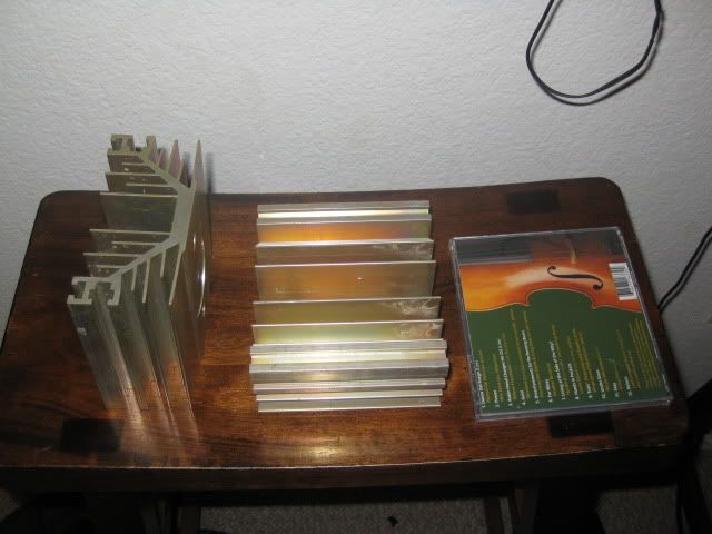
The old heat sinks and the new ones side by side:

Even though the new heat sinks have at least 4 times the surface area, they still get to ~55°C. I'm trying to get the temps down to ambient+15°C , but this seems to be an unattainable goal
frown.gif

I still have plan B though, just like the engineer said: "and if that don't, work use more gun". I have even bigger heat sinks lined up
icon10.gif


I'll need to get this heat problem sorted out before moving on to working on the case. The case I had originally planned for this build became too small, due to the need for increased cooling, but everything else to this point has worked on the first go with only minor problems and even though I have burned ~15 fuses in the process. I have yet to burn out anything on any of the boards.
So THANK YOU ALL
beerchug.gif
(especially runeight). Without the help and information available here (and on cavalliaudio) this build would have been impossible to do. It's so good, that even a first timer builder (like myself) can feel comfortable undertaking something as complex as a balanced EHHA.
 
Apr 24, 2010 at 9:55 PM Post #1,467 of 1,823
Dude.. seriously 55deg is nothing. Let it be. And its not about how big your heatsinks are its the C/W ratio that matters.

And yeah, those smaller heatsinks are not the ones i'd use on a stock EHHA. Use the larger 1.5 inch width ones.

Oh, also those gain resistors needn't have such long leads to socket them in. That is asking for trouble.
 
Apr 24, 2010 at 10:57 PM Post #1,468 of 1,823
The simple problem is that the heatsinks are too small and not the ones spec'd for the project. The simplest solution would be to buy the right heatsinks.
smily_headphones1.gif
 
Apr 24, 2010 at 11:10 PM Post #1,470 of 1,823
^^ yep..the ones in the spec are something like

this.

Quote:

Originally Posted by dBel84 /img/forum/go_quote.gif
indeed, those are skinny runts , mine were a little heftier
biggrin.gif


diy008.jpg


..dB


hah..pales in comparison my EHHA heatsink
tongue.gif


bluebeast003.jpg
 

Users who are viewing this thread

Back
Top