Cavalli EHHA Embedded Hybrid Headphone Amp
Apr 26, 2010 at 3:48 AM Post #1,486 of 1,823
John this build is gonna be amazing!
Seriously out doing me here =P
 
Apr 26, 2010 at 12:39 PM Post #1,487 of 1,823
Quote:

Originally Posted by sachu /img/forum/go_quote.gif
With a 10A DPDT (in you case you will need a 4PDT for balanced) on-on switch, the output of the amp boards go to the input of the switch and from there you will wire one possible output set of pins on the switch to the speaker (put the zobel in there on the binding posts) and then the other set of outputs from the switch go to the headphone out..


Sachu why 10A, I can only find goliath switches with that rating, would this really be needed for the signal path?

... also would an on-off switch be better suited, switching the outputs to the speakers on and off, and leaving the headphone outputs as intended, from the pcb straight to the jack.
With an on-on switch, I’ll have to run the signal output wiring back through the amp to the headphone jack.
 
Apr 26, 2010 at 5:52 PM Post #1,488 of 1,823
Not really, even the miniature ones that are rated for 3A-5A would do.
Don't use the wiring scheme you just mentioned. I ended up blowing up my amp boards with something like that. Use an ON-ON switch for output switching not an ON-OFF switch. An ON-OFF switch is likely to blow your amp boards as well is what I have heard. I will get back to you on why this happens when I can get dBel to jog my memory about it. I am guessing because when you switch it on and off it creates a momentary short in the output (similar to those caused by the TRS jack) blowing your output MOSFETs and resistors.
 
May 4, 2010 at 5:12 PM Post #1,489 of 1,823
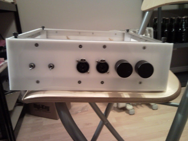
Well, I've been procrastinating a lot about finishing the EHHA. Mostly because I love/hate chassis work. So here's an in progress view of my 50% completion.

SNC00135.jpg


Front Panel:

4PDT switch for Pre Out
4PDT switch for headphone enable

Dual 1/4" Stereo/XLR Mono for Headphone(s)

Dual Stereo/Mono volume controls

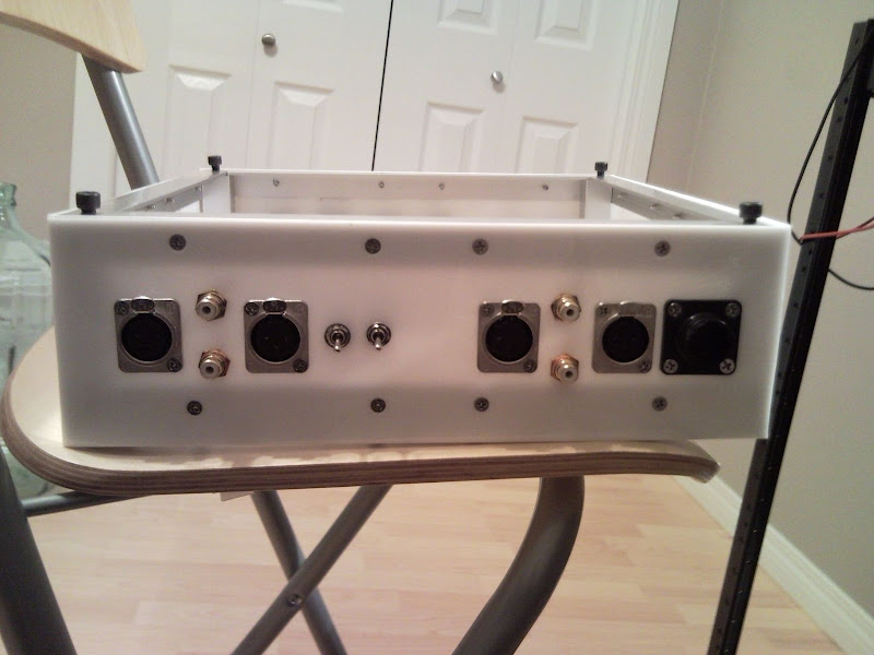
SNC00136.jpg


RCA/XLR input with selector switches. Can convert unbalanced to balanced.

RCA/XLR for unbalanced/balanced pre-out

AMP CPC 9pin power connector to Sigma22/heater supply

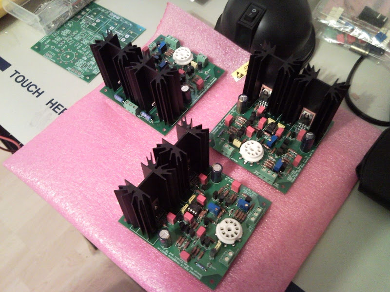
SNC00139.jpg


One EHHA board left to go!!! Then cleanup, mounting, wiring and testing.
 
May 4, 2010 at 5:28 PM Post #1,491 of 1,823
Quote:

Originally Posted by sachu /img/forum/go_quote.gif
wow..nice to see so many EHHA builds and balanced too coming along at once. Sweet work there jjazzyj :beerchug:


I forgot to add, that just like the matching Sigma22/heater power supply chassis the bottom is clear polycarbonate. So all the EHHA boards have bottom mounted LED's for sexy blue under amp glow.

I'm sure that 1 month in that 'feature' will irritate the crap out of me when I watch movies.

Thanks for the feedback sachu! As long as I don't blow up too many MOSFETS when I hook it all up I'll be happy!!! Luckily I have enough extras to build another Balanced EHHA or Balanced B22...
 
May 4, 2010 at 5:32 PM Post #1,492 of 1,823
^^^ lol i don't quite mind the blue and super bright orange LEDs(for amp boards) on mine..it kinda lights up the room at night. The coolness of it hasn't waned for me...yet
wink.gif
 
May 6, 2010 at 12:30 PM Post #1,494 of 1,823
First post on this thread with the new BBS!
 
Well, I did a bonehead manoever last night, soldering one of the trimpots in the wrong orientation. De-soldering plated through holes sucks. Took me 30 minutes to do. I usually use my fingers as a heatsink on the component or in the case of resistors a hemostat. Tested ok after removal so I probably didn't damage it, hopefully.
 
May 8, 2010 at 12:21 AM Post #1,498 of 1,823
Ok, so I got all my wiring hooked up. (One board at a time, though I have to insert two tubes and hook up the heaters for two boards because I'm using 12.6V heater supply). Turned on the heaters and they lit up just fine. Waited a minute then turned on the S22 (which tested @ 28.9V pos and neg) Within 10 sec R4 starts to smoke. I immediately killed the power. Checked for shorts a third time. None. Check resistor values, check transistor values. Tried again, R4 smokes again. Adjusted R6 from what I thought was halfway. Tried again, this time R14 smokes, but not R4 (luck probably). This time hooked up my grippy probes across R14, this was one probe on one side and one on the other side of R14. After waiting a minute with the heaters turned on again, turned on the S22 again. Measure the full 28.9 volts across it, as if something was shorted to GND it seems. S22 is ok through all this BTW. I tested the -30 and +30 inputs on the EHHA board to Star GND and did not get a short but around .500 ohms. Nothing seems shorted.
 
I did not test for shorts after I put the tube in. Is is possible that the tube has a short in it? I'm not sure what is going on at this point since all my values and orientations are correct. Unless IC2/3 are toast.
 
Any suggestions?
 
May 8, 2010 at 12:48 AM Post #1,499 of 1,823
Sorry to hear about the problems Jazzyz..
 
It is really hard to say what could have gone wrong...
 
can you post a pic of the board..a macro shot with a link to it in high resolution would be useful.
 
May 8, 2010 at 12:57 AM Post #1,500 of 1,823
It is possible but unlikely that the tube has a short. This is a very unusual problem in this amp.
 
Are you sure that Q1, Q2, and Q4 are PNP (2SA1145) devices and that Q3 is NPN (2SC2705)? The first thought is that Q2 and Q4 are either shorted or the wrong polarity and are passing too much current. 
 

Users who are viewing this thread

Back
Top