Case-it-yourself DAC kit
May 22, 2009 at 12:11 AM Post #31 of 50
listening to the usb input now.

3552277335_eabcaf565a_o.jpg


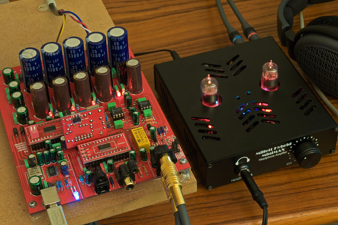
(usb led is blue. that's just funny, to me, for some reason)
wink.gif


each regulator has its own red led near the reg chip. there are THREE 5v regs in addition to the dual 12.

I'm not impressed with the soldering quality - most joints look border-line cold. but the unit does work (so far).

the jacks are all going to need to be replaced - they are the cheapest of the cheap. the 'gold' jacks have gold already flaking off the metal and the dual l/r analog out jack is very flimsy, vertically mounted as it is.

but it is working and the magic smoke stayed inside when I turned it on
wink.gif
 
May 22, 2009 at 4:07 PM Post #33 of 50
it sounds perfectly capable and acceptable. I don't detect any major flaws or problems. passes the smell test, so to speak.
wink.gif


beyond that, I don't get all fussy about which op amp is used as long as its competant. this seems to be that, at least.

I'm listening to some older cd's (from the 80's) that used to be demo'd in stereo stores, a lot, as I recall. fresh aire band. it was good sounding back then but now, my playback system FAR exceeds their best recording noise floor. I'm using a behringer a500 as my spkr amp and a beta22 as my main phones amp. I really can't complain, yet, about this dac's sound. I am using the upsampler module and coax-in (fed from a gamma1 lite, from my PC).

the heatsinks on some of the regs are a bit smaller than I'd like to see. I also notice that the 5v ac input is double bridged and one of my first mods would be to break that connection and go separate, since its easy to find dual 7v windings on toroids these days. I don't understand why they double bridge things - that seems wrong to me.

for install into a case, it really does need all the rear jacks removed and wire-extended to a rear panel. at least that is my plan for my own unit. and there is 1 spare input on the chip (if you look at the pdf schematic) so I'll add a 2nd opto for a total input of: usb/coax/opt1/opt2. you can use existing jumper block and still be able to do that - just tap into one more pin on the receiver chip (8416) and add toslink module, cap and inductor, as is standard.
 
May 22, 2009 at 4:14 PM Post #34 of 50
Quote:

Originally Posted by linuxworks /img/forum/go_quote.gif
I wish someone could show me some sound that entered your home stereo that did NOT pass thru at least 10 op amps (in the studio, at mastering, at many places) before it got to you.

I know you know this but the anti-opamp crowd really makes me grin, sometimes. I guess its a grin..
wink.gif


And more likely 100 or more opamps than 10.

And almost all of them, chips that cost less than a dollar at full retail. ne5532, jrc4580, tl072 - all those jellybeans.

Yes, even your favorite recordings.
 
May 22, 2009 at 7:03 PM Post #35 of 50
As far as soldering goes. I wondered what the quality of that would be since you can tell, even in their sales pics, that a lot of the caps don't sit flat with the board.

An opamp can be less than optimal and still sound just great if you build the circuit around it right. We've all worked with an opamp that was picky in a particular circuit, like the PPA. It isn't necessarily crappy, just difficult. To be anti-opamp you'd have to only listen to music published before recording studios changed out all their tube stuff and you couldn't listen to any music that had been digitized since all of these DAC chips have some sort of opamp built into them. It might not be strong enough to power headphones, but there is one there!
 
May 22, 2009 at 8:04 PM Post #36 of 50
Quote:

Originally Posted by DKJones96 /img/forum/go_quote.gif
As far as soldering goes. I wondered what the quality of that would be since you can tell, even in their sales pics, that a lot of the caps don't sit flat with the board.


I'm not impressed. I would not send this out under my name, if that means anything.

the thought had crossed my mind to ask the seller if a special order of a bare board would be possible. I'm half serious, too.

almost no joint looks good; they all look cold, some don't have enough solder, some have too much.

parts placement is passable but not 'custom made' passable.

I also would use molex offboard connectors and let the user choose the rear panel jacks they want to use. that makes diy building easier and also lets us choose the quality of the jacks. none of the jacks is even remotely useable for longer term installation - and coming from me who is NOT usually fussy about connectors, take that fwiw
wink.gif
the toslink is fine but all else need replacing. the stuff that comes on the board for rear mount is 'demo use only' the way I see it. verify the machine works, then remove the junk and put at least mid-grade connectors on.
 
May 22, 2009 at 8:14 PM Post #37 of 50
Quote:

Originally Posted by linuxworks /img/forum/go_quote.gif
the thought had crossed my mind to ask the seller if a special order of a bare board would be possible. I'm half serious, too.


I just asked both users selling this if they offer unassembled kits. The hardest soldering job would be the little SMD chips but I'm sure those could be pre-done if we REALLY asked for it. Should still come out cheaper as they don't have to solder anything.

Even though it would be a paint by numbers build like the PPA, I still like taking out my iron to solder stuff for a few hours.
 
May 22, 2009 at 8:22 PM Post #38 of 50
it would also be neat, while we're dreaming about hacking this, to have some alternatives that plugin to the 2 or 3 sockets (big chip sockets).

I'm guessing that the red is a 'series' and that the main and little boards are all red to match and maybe (??) a black one from an older series may not be pin compatible? maybe not - but one of the files was named 'red1' and my board set is all red, yet the ebay pics ALL show black, from all vendors. so I really do wonder if some minor or even major changes happened and they went with colors to keep things straight? not sure.

all the hard soldering is on the chip carriers, other than the pcm usb chip. even THAT should have been on a chip carrier (if I had my way).

I also really would have liked more room for bigger heatsinks on the regs. really. they seem a bit toasty to me with their diminutive heatsinks. at least they're all lm317 class, so that's kind of nice compared to what they could have used
wink.gif


and if the vendor wants input (heh) - a pulse trafo on the coax is not really OPTIONAL, in my book. yet another reason to panel-mount the coax-in jack and add a pulse trafo for isolation. and remember not to ground the rca shield on coax-in's.
 
May 22, 2009 at 8:33 PM Post #39 of 50
Looking at the pictures of the completed board and the schematics it looks like they used a cap to isolate the signal line of the coax in lieu of a transformer which I guess does provide DC isolation.

Initial start-up has gotta be hell on those regs. They've got a large cap bank in front of them feeding the current they need to surge fill the 2200uF caps and circuitry behind them.
 
May 22, 2009 at 9:11 PM Post #40 of 50
the way AMB has his y1 for coax-in, that's pretty much the correct model (from past experience in spdif). there is a blocking cap as well as a pulse trafo. and an R or two to try to keep things 75ohm (at least try).

the pulse trafo is the important part and they left that out. really too bad. its kind of a blemish and they saved, what, a whole $2 on that trafo? oh well.
 
May 23, 2009 at 8:39 AM Post #42 of 50
Coax S/PDIF should have a pulse trafo on the receiving end as well as the transmitting end, period. Capacitor coupling is also required, which blocks DC, but the pulse trafo provides galvanic isolation. The S/PDIF transmission line, when isolated on both ends and "floats" with respect to ground, becomes like a balanced line with improved CMRR.

Unfortunately, many digital sources (especially cheap ones) do not have a pulse trafo at its coax output, and if the DAC's coax input also lacks a pulse trafo, then not only would the S/PDIF signal integrity be compromised, a ground loop might also be introduced.
 
May 23, 2009 at 1:05 PM Post #43 of 50
perhaps somebody should make up a digital cable with pulse trafos and ancillary circuitry built-in at both ends (i think this has been done before, but have not seen one in years.......

the parts could be built iinto small boxes on each end of the cable, and priced accordingly.
wink.gif


or, would the compromised send and recive circuitry on the equipments' boards defeat the purpose?
 
Jun 4, 2009 at 4:01 AM Post #45 of 50
(from the other thread)

ah, perhaps they ship the red boards then.

Quote:

Originally Posted by linuxworks /img/forum/go_quote.gif
so far, this 'red dac' (noodle++) is pretty good, I think. no idea about long-term reliab - but so far, its my main listening dac and I've not found anything to complain about.

it was in the $100 range (shipped) and needs only a good trafo (12v dual winding and a STRONG 5v winding, close to an amp or more, I would guess). I'm using a pair of toroids since I opted NOT to get the vendor's own trafo (honestly, I don't trust china made trafos, not for power line stuff!)


If I'm not mistaken, in the listing they include the trafo as part of the assembled kit, do they not?
scratcho.gif
 

Users who are viewing this thread

Back
Top