Carl's DIY adventures
May 6, 2021 at 7:06 PM Thread Starter Post #1 of 35

carlman14

100+ Head-Fier
Joined
Dec 10, 2018
Posts
231
Likes
576
Location
WA
Hey all, I have really leaned-in to the DIY scene over the last year, and I wanted to create this thread to share some of my DIY amplifier adventures. I have built cables, amplifier kits (bottlehead), restored vintage amps, but never built one from scratch like this. It was so much fun and I've learned so much doing this project.

This amp is based on the RH84 v2 circuit shown here: http://rh-amps.blogspot.com/2013/02/rh84-amplifier-revision-2_26.html . Much like the ZMF pendant, it runs on EL84 output tubes and a 12AT7/12AU7 input tube.

I have a tendency to crave doing things in a way that makes them unique... so I made the following changes to the design:

1. Modified the power supply to use two 6AX4 damper diodes instead of a more "standard" rectifier.
2. Added volume control.
3. Added a switch to switch between pentode and triode-strapped mode for the EL84s.
4. This is a headphone amplifier. I haven't seen this circuit built as a pure-headphone amplifier before.

Some specs:
- Outputs about 4W into 32 and 120 ohm headphones in pentode mode, or about 1.5W in triode mode.
- OPTs: custom by electraprint with 32 and 120 ohm secondaries.
- PT: Lundahl LL2741
- Headphone jacks are inspired by ampsandsound by having separate jacks for 32 and 120 ohms.
- PSU is CLCRC with a B+ of about 315V.
- Miflex coupling caps.
- 12AT7 driver can be swapped out for a 12AU7 for less gain and improved noise floor at the cost of some power.
- Chassis is from Landfall Systems

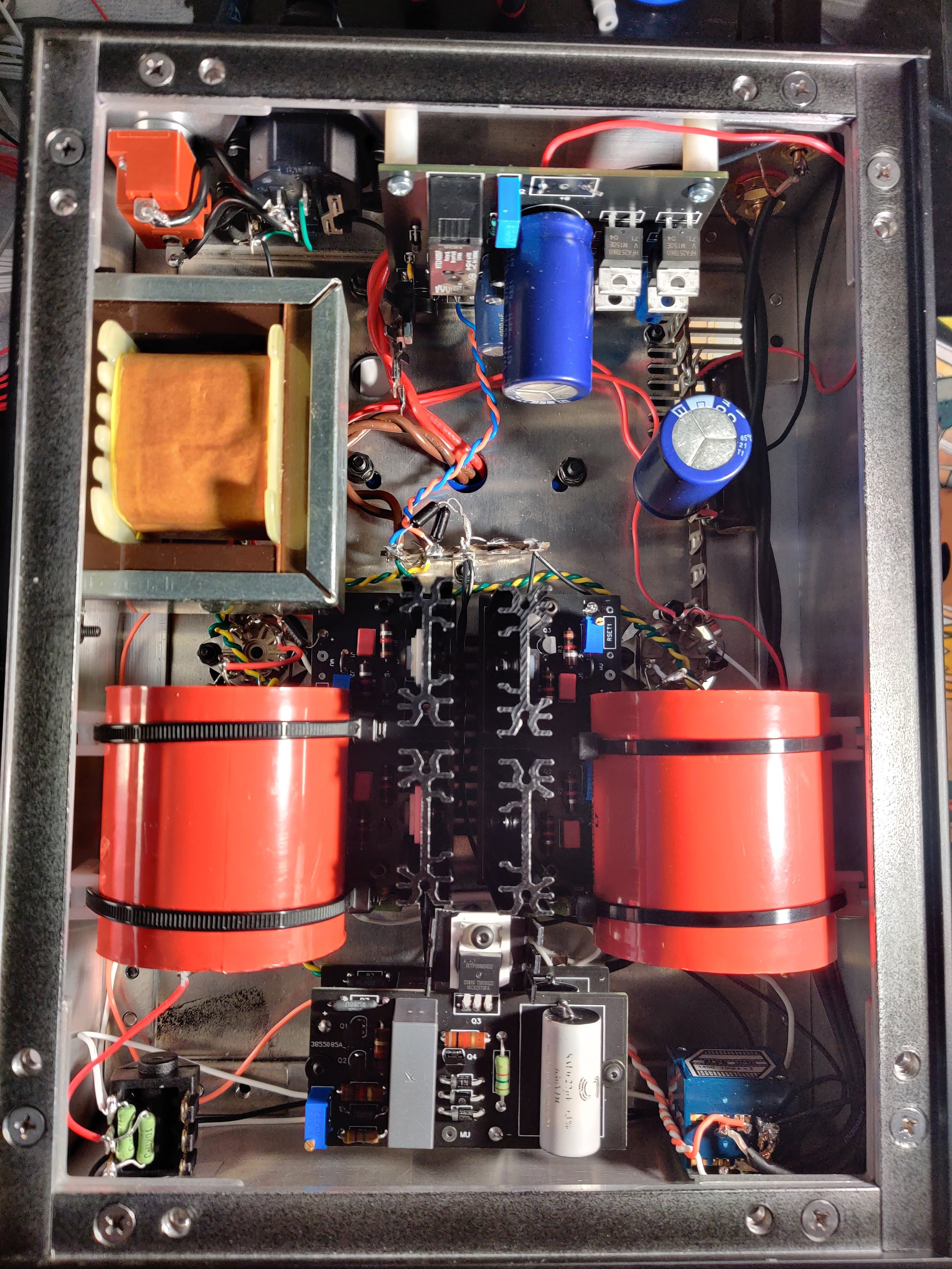
Overall I am so pleased with how this turned out! It sounds amazing and is extremely quiet. It is definitely on-par with my Mogwai SE. The inside is a little messy and some of the wire colors don't make sense because I ran out (like the rainbow of colors going to star-ground haha), but overall I'd say it's not bad.

Best combinations of outputs and headphones I've discovered so far:
- Pentode mode and 32 ohm jack with hard to drive planars (Hifiman Arya). My Arya sounds incredible with the high output power.
- Pentode or triode mode with 32 ohm jack for more sensitive high impedance dynamic headphones (ZMF).
- Triode mode with 120 ohm jack for high impedance dynamic headphones (ZMF)

Consider myself addicted to DIY. My next project will be more involved... I'm going to have to do a lot of design work instead of following a well-known circuit next time :)

Ok, Here's some pics!

RH84.jpg
RH84_back.jpg
RH84_inside.jpg
 
Jun 5, 2021 at 1:09 PM Post #2 of 35
Making some progress on my next project! This is going to be a lot of fun, and should turn out incredible. Originally, I was going to build this all-EL3N amplifier I found here: https://www.dhtrob.com/impressies/el3n_se_sakuma.php. It looked interesting because it seems very similar to Glenn's GEL3N amp. But then I went down the "what if" rabbit hole, iterated on the design a ton, and now have an interesting project on my hands.

There are 3 goals of this project:
  1. Have an all-EL3N based amplifier
  2. Have massive tube rolling capabilities
  3. Be able to replace my Ampsandsound Mogwai SE by being able to roll output tubes that it uses.

Some high-level specs:
  • Output transformers will be 5K:8/32 from monolith magnetics
  • B+ is maida-regulated
  • Input tubes will be gyrator-loaded
  • Input tubes: EL3N, C3g, 6J5 (and equivalents), EL33 (octal version of EL3N)
  • Output tubes: EL3N, EL33 (and equivalents), EL34, KT66/77/88, EL38, 6V6, 6L6GC
  • 1W to ~4.5W output power before clipping, depending on the tubes used and HV supply I decide on.

There will be a switch to optimize for EL3N/EL33 and the rest of the output tubes. The EL3N has a different happy operating point than the other tubes. The switch will switch-in a resistor on the maida regulator that controls output voltage to change the B+ from about 300V to 250V.

There will be another switch for input tube optimization. It will change the bias from -4V (6J5, EL3N) to -2V (C3g).


TODO: I am debating on a couple different layouts for the chassis:
  1. Have sockets for all tubes, with switches that turn on/off sockets that are not in use. This will allow me to populate all tube sockets (which would look awesome!), and just use the switches to select which input/output tubes are active. This would be done while the amp is off of course.
  2. Do not include EL3N sockets and use adapters for them. The downside is I would need adapters, but the top plate is cleaner looking.

Here's some pics showing potential layouts, the current schematic (not done), and some output tube operating points with a 420 ohm cathode resistor.

Design 1.pngDesign 2.pngEL34.pngKT88.pngEL3N_output_operating_point.png
 
Jun 8, 2021 at 4:36 PM Post #3 of 35
I don't know how I missed your first post, very nice work Carl! :beerchug:

Can you tell me a little more about the 6AX4 damper diodes? I know the original 6AX4 from the 40s has a bit of a reputation for iron eating, but the newer GTs from the 60s are more robust. I was digging around a bit trying to see if they have a diode mod like the 5AR4 but didn't see much. I'm working on an SP14 that uses one.

I'm assuming this design isn't too different from the ZMF Pendant based on the DIYTube Budgie SE: http://www.diytube.com/phpBB2/viewtopic.php?t=5563 . The ZMF has a noval rectifier that wasn't in the original design. If you search google you can find my Budgie SE with some Russian silver micas, as a trade member I'm not allowed to link it.

Did you just add 90 ohms of resistance to the left and right + coming from the 32 ohm output to get the 120 ohm output?

-----------------------------------------

I'm very excited about your next build. I love EL34s and their lush midrange. Will you be using Pete Millett's Maida boards?
 
Last edited:
Jun 8, 2021 at 6:15 PM Post #4 of 35
Thank you for the kind words!

Can you tell me a little more about the 6AX4 damper diodes? I know the original 6AX4 from the 40s has a bit of a reputation for iron eating, but the newer GTs from the 60s are more robust. I was digging around a bit trying to see if they have a diode mod like the 5AR4 but didn't see much. I'm working on an SP14 that uses one.

Damper diodes are pretty new to me. I discovered them when planning this project... and heard great things about them acting as rectifiers for audio applications. That combined with my desire to do things in a unique way and it was an easy sell :) . I hadn't heard about the iron eating problem, but I haven't encountered that at all. The 6AX4 is loved by folks who use damper diodes (VinylSavor in particular), so I'm not too worried about having problems with them. They are set up in a hybrid bridge rectifier (2 SS diodes, 2 tube diodes). This allows the use of a non-center tapped transformer while still having the benefits of a tube rectifier.

I'm assuming this design isn't too different from the ZMF Pendant based on the DIYTube Budgie SE: http://www.diytube.com/phpBB2/viewtopic.php?t=5563 . The ZMF has a noval rectifier that wasn't in the original design. If you search google you can find my Budgie SE with some Russian silver micas, as a trade member I'm not allowed to link

I imagine it's very similar to the Pendant, though I'm not sure if the Pendant uses plate-to-plate feedback like this design does.

Did you just add 90 ohms of resistance to the left and right + coming from the 32 ohm output to get the 120 ohm output?

Nope! The OPTs were custom made by Electraprint, and have both 32 and 120 ohm taps natively. The resistors you see on the 120 ohm output are 4.7k resistors in parallel with the jack (They go from L and R to ground on the OPT). The headphone jacks are switched, so when a headphone is plugged into the 120 ohm jack, those 4.7k resistors are switched out of the circuit. When a headphone is unplugged, the 4.7k resistors provide protection for the OPTs. For the 32 ohm jack, there are no resistors. When using the 32 ohm jack, the 4.7k resistors on the 120 ohm jack are still present to the OPT, but they are high enough resistance that they are effectively "invisible" and have no effect when a headphone is plugged into the 32 ohm jack.

Will you be using Pete Millett's Maida boards?

I will be using the 21st century maida regulator from Neurochrome!
 
Jun 9, 2021 at 2:26 PM Post #5 of 35
Sorry I misspoke Carl, it's the 6X5 rectifier, not the 6AX4 that have that particular issue. Adding the SS rectifiers should help increase the life of the tubes, which is always nice.

I only know the above issue as I'm building an SP14 preamp which uses a 6X5. Don Sachs actually builds the SP14 however has modded it for a 6BY5. He also uses a pair of the 21st century Maida in one of his amps.

Thanks for the info on Electraprint. I'm really glad they're still in business. Them and Heyboer are the only two firms I know of that will make you a one-off output xformer. Appreciate the explanation on the resistor config as well.
 
Jun 11, 2021 at 3:47 PM Post #6 of 35
Nice looking amp you got there.

As for your next project, I would strongly urge you to forget about trying to design any amp around tube rolling. You end up making an amplifier that is either exceedingly complicated with excessive control units, or you make an amp that is a jack of all trades and a master of none. Either way, it ends up being a huge mess.

You should consider sticking with a EL3N driving a EL3N. I would also urge you to look into direct coupling since you want to use a gyrator.

If you need something with more power for speakers, just build a dedicated set of speaker amps. Preferably mono blocks. A good 300b amp will allow you to replace that ampsound amp in short order.
 
Jun 11, 2021 at 7:03 PM Post #7 of 35
Nice looking amp you got there.

As for your next project, I would strongly urge you to forget about trying to design any amp around tube rolling. You end up making an amplifier that is either exceedingly complicated with excessive control units, or you make an amp that is a jack of all trades and a master of none. Either way, it ends up being a huge mess.

You should consider sticking with a EL3N driving a EL3N. I would also urge you to look into direct coupling since you want to use a gyrator.

If you need something with more power for speakers, just build a dedicated set of speaker amps. Preferably mono blocks. A good 300b amp will allow you to replace that ampsound amp in short order.

Thanks for the feedback! I appreciate it. The reason for the tube rolling was because I wanted to make use of the tubes I already had (plus I already ordered the OPTs with specs intended for this amp). I've already dialed-down the complexity a bit, because like you said... there were too many controls going on.

Just to play devil's advocate for a sec, I want to explain what I have so far, because I think (I could be wrong) that everything is looking ok with regards to tube rolling.

First, the reduced complexity: If I move forward with tube rolling, I'm leaning toward the route of using EL33 tubes instead of EL3N (or using EL3N -> EL33 adapters). This will remove 4 tube sockets as well as the necessary switches to turn off/on those sockets. I also might ditch the C3g support, eliminating the input tube selector switch as well.

Second, the operating point of the output EL3Ns (Or EL33s) is virtually the same as the original design, with a slightly lower 5K OPT primary. Same 420 ohm cathode resistor and same 250V anode voltage. The only switch I have left at this point is to switch between 250V and 300V B+. 300V is for the rest of the output tubes I mentioned (KTxx, EL34, etc). The switch would add/remove a resistor in parallel on the maida regulator to adjust the output voltage. With a 420 ohm cathode resistor and 300V plate voltage, operating points for all other output tubes seem very reasonable. The current drawn from the other output tubes range from ~50mA to ~72mA depending on the tube.

I'm finding the operating points with this incredibly handy load line calculator, adjusting the bias current until I hit 420 ohms of cathode resistance for each tube: https://www.vtadiy.com/loadline-calculators/power-stage-calculator/

So, on paper, It looks like I could get the intended all-EL3N experience while also being able to roll the other mentioned output tubes at solid operating points. Feel free to correct anything that's wrong or provide suggestions. I'm here to both show and learn!

Regarding direct coupling: I'll definitely look into that! I don't know much about it.
 
Jun 11, 2021 at 8:20 PM Post #8 of 35
Thanks for the feedback! I appreciate it. The reason for the tube rolling was because I wanted to make use of the tubes I already had (plus I already ordered the OPTs with specs intended for this amp). I've already dialed-down the complexity a bit, because like you said... there were too many controls going on.

Just to play devil's advocate for a sec, I want to explain what I have so far, because I think (I could be wrong) that everything is looking ok with regards to tube rolling.

First, the reduced complexity: If I move forward with tube rolling, I'm leaning toward the route of using EL33 tubes instead of EL3N (or using EL3N -> EL33 adapters). This will remove 4 tube sockets as well as the necessary switches to turn off/on those sockets. I also might ditch the C3g support, eliminating the input tube selector switch as well.

Second, the operating point of the output EL3Ns (Or EL33s) is virtually the same as the original design, with a slightly lower 5K OPT primary. Same 420 ohm cathode resistor and same 250V anode voltage. The only switch I have left at this point is to switch between 250V and 300V B+. 300V is for the rest of the output tubes I mentioned (KTxx, EL34, etc). The switch would add/remove a resistor in parallel on the maida regulator to adjust the output voltage. With a 420 ohm cathode resistor and 300V plate voltage, operating points for all other output tubes seem very reasonable. The current drawn from the other output tubes range from ~50mA to ~72mA depending on the tube.

I'm finding the operating points with this incredibly handy load line calculator, adjusting the bias current until I hit 420 ohms of cathode resistance for each tube: https://www.vtadiy.com/loadline-calculators/power-stage-calculator/

So, on paper, It looks like I could get the intended all-EL3N experience while also being able to roll the other mentioned output tubes at solid operating points. Feel free to correct anything that's wrong or provide suggestions. I'm here to both show and learn!

Regarding direct coupling: I'll definitely look into that! I don't know much about it.


Your plan ultimately depends on how you want to adjust the bias current. This is perhaps the biggest pitfall with an amp like this.

First there is a safety concern. If you have a pair of KT88s in your amp biased att 80ma, and you forgot to throw a switch before swapping to some EL3Ns, you would damage if not destroy your EL3N tubes. If you threw a switch to change the bias without first turning off the amp, you could potentially damage something as well.

Even if you are really good about checking everything before powering up your amp, schiit happens. You will most likely blow something up at some point and it won't be cheap to fix.

Then you have the sound quality issue. In order to get the best sound out of your amplifier you should really have a single cathode resistor wired directly to your tube socket and ground. Adding a switch in there will degrade the sound. Some people will fight me on that point until they are blue in the face, but the truth is that any modification (which is a polite way of saying 'extra crap') to the cathode circuit makes a huge difference in sound quality.

I would also be so bold as to tell you that most of the tubes you are looking at swapping around, aren't all that great for small audio signals. Don't get me wrong, I like all of the tubes you have listed. In fact I have made an amp that can accept all those tubes (which is part of the reason I am warning you not to do it lol) and I still listen to it from time to time. But you probably won't bother with your other tubes after hearing a proper sakuma style EL3N or EL33 amp. And once you step into the world of DHT tubes, you probably won't even touch your EL3N amp either.

In fact, considering the quality of those monolith magnetic transformers, I would urge you to strongly consider ditching everything and jump straight to using a 45. Keep in mind the EL3N grew in popularity because it was considered a cheap alternative to the 45. Now that it has become popularized, it is actually more expensive than the 45 tube these days which is why you don't see more of them around.
 
Jun 11, 2021 at 9:23 PM Post #9 of 35
First there is a safety concern. If you have a pair of KT88s in your amp biased att 80ma, and you forgot to throw a switch before swapping to some EL3Ns, you would damage if not destroy your EL3N tubes. If you threw a switch to change the bias without first turning off the amp, you could potentially damage something as well.

Even if you are really good about checking everything before powering up your amp, schiit happens. You will most likely blow something up at some point and it won't be cheap to fix.

Then you have the sound quality issue. In order to get the best sound out of your amplifier you should really have a single cathode resistor wired directly to your tube socket and ground. Adding a switch in there will degrade the sound. Some people will fight me on that point until they are blue in the face, but the truth is that any modification (which is a polite way of saying 'extra crap') to the cathode circuit makes a huge difference in sound quality.

I think there was some misunderstanding here. I planned on using the 420 ohm cathode resistor for every output tube. The switch I mentioned before alters the HV supply coming from the maida regulator from 250V to 300V. It does not alter the cathode resistor. 420 ohms supports the original design's EL3N tubes at 250V and provides good operating points for other tubes at 300V according to that loadline calculator I linked earlier.

The mA range I mentioned for the other tubes is all with that 420 ohm cathode resistor and 300V plate voltage. 300V and 420 ohms puts the EL34 at about 53mA draw, and puts the KT88 at about 71mA draw. But with a 250V supply and that same 420 ohm resistor, the EL3N draws about 20mA. All good there.

As far as safety goes, I definitely agree that operation needs to be safe. With what I said about the switch, accidentally having the switch in 300V mode would put the EL3N at about 25mA with the 420 ohm resistor. That's a bit above it's recommended operating point, but it's still below the max dissipation of the tube. The EL3N would be a little unhappy, but I don't think it would be nearly as catastrophic as pumping 80mA into an EL3N haha.

I would also be so bold as to tell you that most of the tubes you are looking at swapping around, aren't all that great for small audio signals. Don't get me wrong, I like all of the tubes you have listed. In fact I have made an amp that can accept all those tubes (which is part of the reason I am warning you not to do it lol) and I still listen to it from time to time. But you probably won't bother with your other tubes after hearing a proper sakuma style EL3N or EL33 amp. And once you step into the world of DHT tubes, you probably won't even touch your EL3N amp either.

In fact, considering the quality of those monolith magnetic transformers, I would urge you to strongly consider ditching everything and jump straight to using a 45. Keep in mind the EL3N grew in popularity because it was considered a cheap alternative to the 45. Now that it has become popularized, it is actually more expensive than the 45 tube these days which is why you don't see more of them around.

For the record, I plan on making a DHT amp (probably 300B) at some point. I was waiting until I got a little more experience under my belt because I want it to be perfect. I hear you loud and clear about tube choice. I was really hoping to use all the tubes I currently have on hand, because I do like them quite a bit. At the very least, if I end up preferring the sakuma-style EL3N amp, this project will function perfectly fine for that purpose... and will hold me over until I tackle a DHT project.

You've given me some things to think about for sure :)
 
Jun 11, 2021 at 9:41 PM Post #10 of 35
Ah. I see. Good stuff. All I would caution you to do is take the time and draw your load lines on the triode graph of every tube you want to use. Just as a double check of that software. Although I get the feeling you probably already have :beerchug:


By giving up on trying to get max power out of the tube, it certainly makes switching tubes around easier. But do understand that by running the tubes at lower than normal current, you might see a rise in the plate impedance which might raise your overall distortion characteristics. It's not a big deal whatsoever, but keep that in mind as you play around with your tubes. If you find a tube you really like, or really dislike, take a second to check the bias for that tube. You may want to alter the bias a bit to accommodate that tube.

As far as DHT tubes go. Don't even think about it. Just use a rod coleman regulator for the filament and use them like any other tube. We don't live in the dark ages anymore. It's pretty easy to play around with DHTs these days. :sunglasses:
 
Jun 12, 2021 at 12:17 AM Post #11 of 35
Yeah, I've utilized my Microsoft paint skills to draw many load lines lol.

As it is now, the max unclipped power I'm looking at is 4.5W using the KT88. 2-3W with other tubes, and 1.5W with EL3N. I could push it to ~6.5W with KT88s if I run them up to 350V. I almost exclusively listen to headphones so this is already ridiculous overkill for headphone use.

Good to know for those DHT tubes. Because I'm still learning, I'm not in any hurry to chase a specific tube, and I'm taking my sweet time soaking up everything I can. I'm mostly taking each project as an opportunity to learn and try something I haven't done before. The OPTs I got could work for 45, 2A3, or 300B. So who knows what I'll end up with in the end. Either way, it'll be fun :)
 
Jun 17, 2021 at 1:31 PM Post #12 of 35
I spent this last week diving head-first into LTSpice. This tool is absolutely amazing! I have the whole schematic modeled, including the gyrator load on the driver tube. There's a couple temporary parts to the schematic: First, I'm using a 6SN7 as the driver for now because I couldn't find a 6J5 or EL33 model. Second, I modeled a classic CLCRC power supply because I didn't want to try modeling the maida regulator. This PSU should be fine for now for modeling purposes.

I modeled a variety of output tubes, and so far the results are looking good. Some high-level numbers from my simulations:
  • Max output power: 3-5 watts depending on the output tube (tested with 6L6, EL34, KT66, and KT88).
  • Distortion with less than 10 mW into 300 ohm headphones: 0.25% - 0.5%. Despite the popular marketing that an amp can put out X watts of power, headphones will only ever use around 1-5mW of power before they're too loud for the user.
  • Distortion at max power: 5% - 8%.
I'm not putting too much stock into the numbers yet, as I'm still learning the intricacies of LTSpice, and I'm at the mercy of models I found online for the various mosfets in the gyrator. I don't know how accurate those models are. But they're good ballpark estimates.

I feel like I've learned so much from tinkering around with LTspice. Distortion levels, frequency response, effects of different tubes on gain and output power, different kinds of analysis that gives more insight into how tube circuits work, and much more. It's pretty amazing.

Here's the current schematic:
schematic.png

Here's an example of a distortion graph (Measured with 5mW into a 300 ohm load):
distortion.png

The wheels are still turning regarding some sort of DHT integration. If I wanted to add some DHT flavor to my amp, I could use the 26 tube as a driver. It has a lower gain than the other input tubes I was considering, so I'd be limited to the EL33 or EL38 if I wanted to go that route. I'm also looking into toroidal power transformers. The output transformers I ordered are enormous, and I could decrease the footprint of the amp if I fit a torroidal PT under the chassis.

At this point I'm just messing around until my output transformers get here. Once I get those, I'll be able to start! Can't wait!
 
Jun 18, 2021 at 9:07 PM Post #13 of 35
I wanted to share a couple of the new things I'm trying in this build: the gyrator and SiC bias boards from Bartola Valves.

Gyrators are both similar and different to CCS loads. A CCS sets the DC current for the tube and provides a very high AC impedance, which creates a flat loadline. That in turn reduces distortion in that stage of the amp, assuming you're setting your operating point correctly. A gyrator (technically called hybrid-mu follower) sets the anode voltage for a tube rather than the current. But it also provides a high AC impedance to the tube, creating that flat loadline that a CCS provides. In my original design, this is what allows me to roll both 6J5 as well as EL33 as input tubes. If I have the anode voltage set to 150V with the gyrator and -4V of bias, a EL33 will draw about 18mA, and a 6J5 will draw about 6mA, both with minimal distortion with the flat load lines. These are happy operating points for both input tubes.

Below the gyrator boards are the SiC bias boards. These are flexible bias boards that allow setting the bias voltage from -1 to -6V depending on how many SiCs are installed. I hadn't heard of SiC bias before this project, so it'll be fun playing around with it. According to the creator, SiC bias sounds really good, and it also removes a capacitor from the signal path! Definitely worth playing around with.

IMG_20210617_095724.jpg

On another note from my own journey and learning: I have found that the usual advice when learning about tube amps is to pick up Morgan Jones' Valve Amplifiers book. I've read through a lot of it at this point. While this is an incredible resource and is considered one of the best books on the subject, it's just too dense and technical for complete beginners in my opinion. It can be very daunting and off-putting if you know nothing about the subject. Here are three sites that I discovered along the way that are much more readable for beginners and definitely helped jump-start my understanding of tube amps:

- https://www.analogethos.com/blog
- https://wtfamps.com/welcome/
- https://www.vtadiy.com/

For the record, I still recommend Morgan Jones' book. But maybe save that for after you've learned a bit from other sources first.
 
Jun 27, 2021 at 8:37 PM Post #14 of 35
My output transformers arrived! These are the biggest and nicest transformers I've ever had. I'm really excited to use them.

IMG_20210625_154718.jpgIMG_20210625_154724.jpg

Some other minor progress has been made. Here are the stuffed gyrator PCBs for the input tube loads:

IMG_20210627_122816.jpg

And here's my latest chassis diagram. I'm still playing around with the PSU configuration. I haven't decided if I'm going to include damper diodes or not. Tube rectifiers are a little pointless when using regulated HT, but I'm a sucker for the tube glow. The MM transformers are so large that I think I will use a toroidal PT under the chassis. This will allow me to shrink the width of the chassis by an inch or two and not have an overly-large amp. I'm just hoping that doesn't induce any hum.

design_6_27.png
 

Users who are viewing this thread

Back
Top