


Jam_Master_J
Headphoneus Supremus
- Joined
- Aug 25, 2003
- Posts
- 1,851
- Likes
- 13
Here's the full guide. Sadly I lost a couple pics that showed more info about routing wires but hopefully it's still useful for people.
[size=small]beyerdynamic DT880 Re-Cable[/size]
Tools/Materials
Soldering iron
Multi-meter
Appropriate wire(Mogami 2534 in my case)
Appropriate termination(Canare F12 in my case)
Heatshrink(optional)
Nylon covering(optional)
Heat Gun(optional)
Disassembly:
The first step in re-cabling the dt880s is to disassemble the headphones. This process should work for any of the 770/880/990 series beyer headphones.
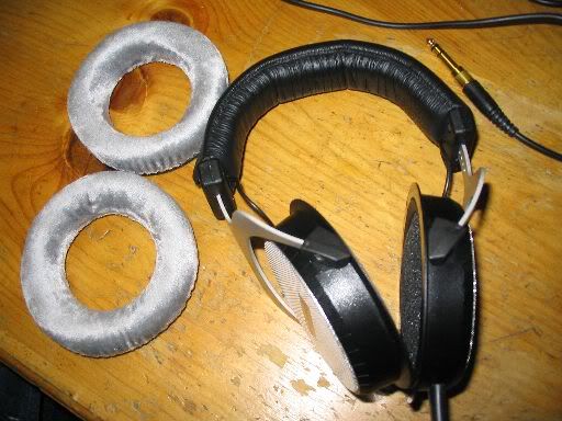
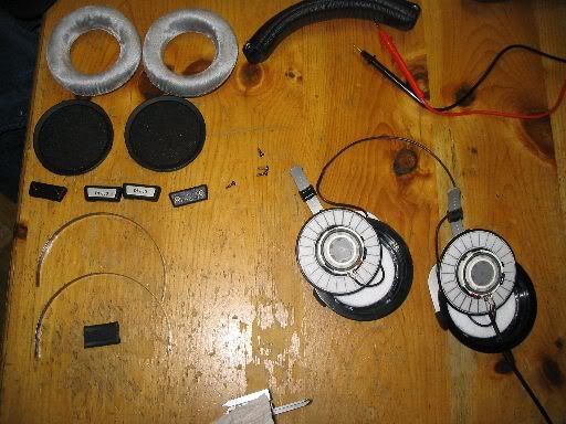
1) Remove the velour ear pads.
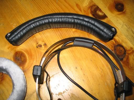
2) Remove the padded headband. First you'll need to unbutton the fasteners and then it should come off easily.
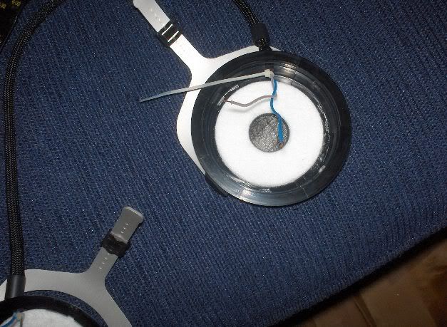
3)Unscrew the tabs that say "DT880 L/R". You will need a philips screw driver for this. Remember to set the parts in a safe place. This allows us to work with the drivers separately from the headband.
4)Remove the driver. The best way to accomplish this is to use a small thin metal blade such as in a pocket knife. Simply wedge the blade in along the out circumferance of the driver and wiggle it a bit. The protective mesh should come out first and then the driver itself. Use caution here, replacing a driver could be expensive.
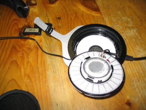
We now have the headphone disassembled and ready to start operating on.
The Wiring
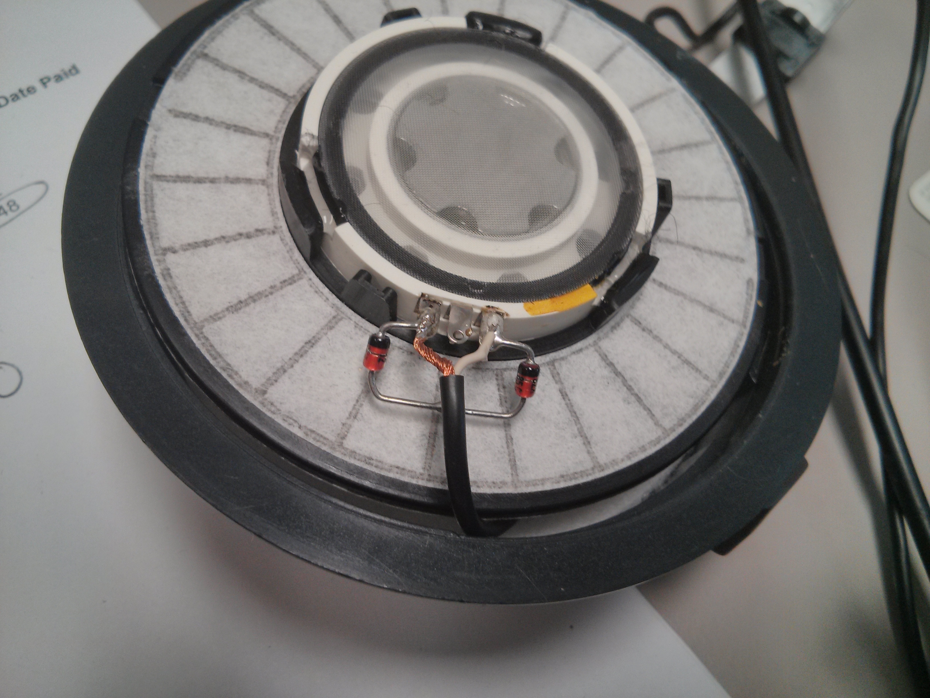
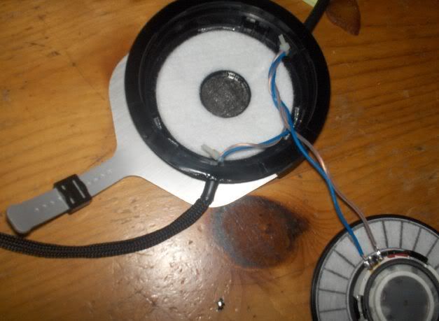
One of the first things you'll notice upon exposing the dt880 drivers is that each driver has 3 terminals rather than the standard 2 terminals.
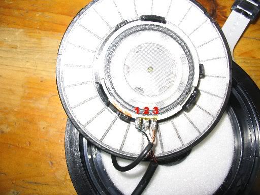
The center terminal is just used as a neat way to splice the signal cable for the opposite earcup and is used only on the left driver. In my case, I will use 4 conductor cable and will therefore be bypassing the center terminal on both drivers. To me, this way is less degrading to the signal.
For the above driver(left driver), terminal #1 is the positive connection, terminal#3 is the ground terminal and #2 will not be used by most people.
The red/gold mark on the driver indicates the positive terminal. On the right driver the terminals are opposite. This can be seen by the mark. This is something very important to watch for, don't assume both drivers have the positive terminal in the same position, look for the mark.
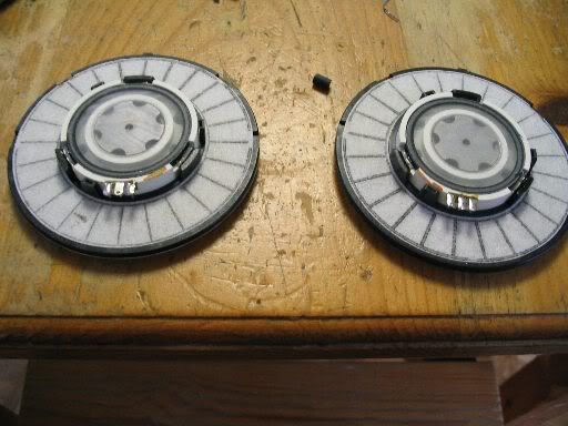
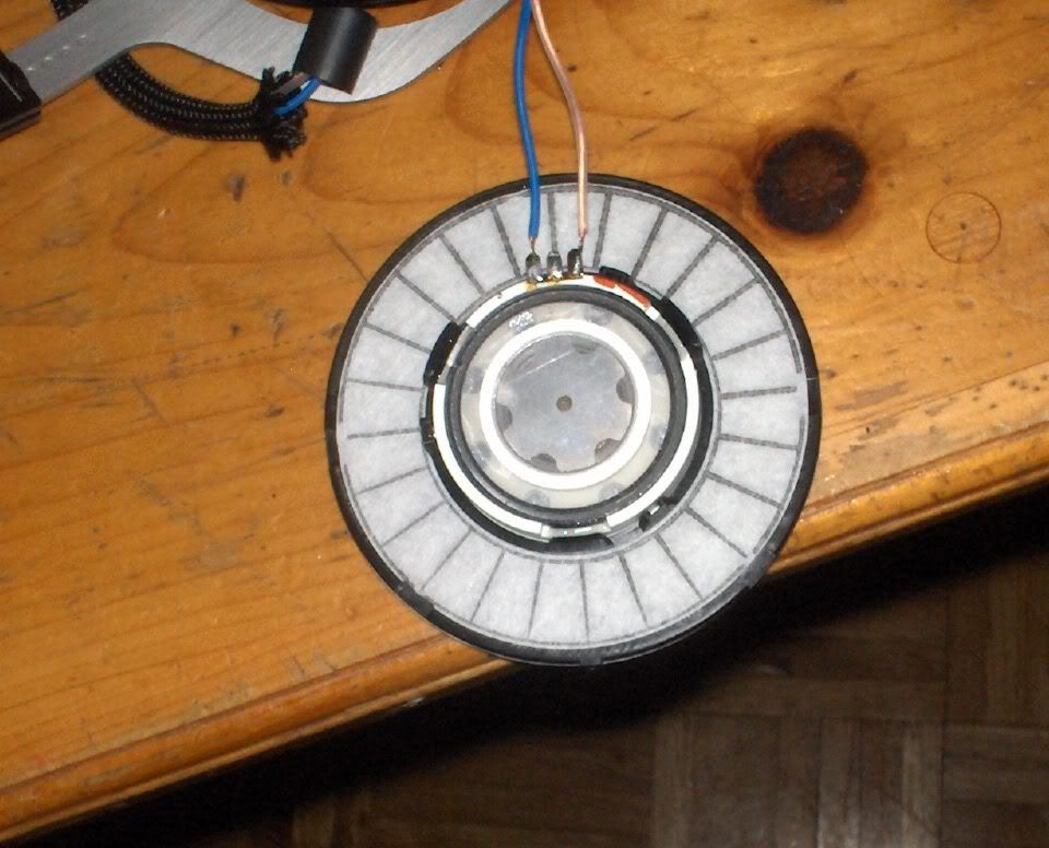
Here are both drivers completely desoldered from the stock cable(right driver is on the left side of the picture):
Now, after you completely remove the stock cable you will need to prepare your new cable. In my case, using Mogami wire here is my procedure: Strip the outer sheathing and shielding off two feet of the Mogami wire. Of the revealed wires there will be two blue and two white. Cut one of each color to a short length of about 6 inches and leave the other two wires uncut.
All 4 of the wires will enter the left earcup from the bottom. The two long wires take the extra journey from the left earcup to the right earcup. It is kind of important that the length of wire between the cups be approximately 16". This measurement works well with the headband so aim for that as a result. Once you get the 16" of separation you will have some extra cable in your right earcup. If you've got more than 5" or so of wire going into the right earcup you can go ahead and trim it down a little. Make sure that if you are adding heatshrink or anything to the connecting cable that you do it now before we start securing things.
Once you start getting your cables in place you may as well implement some strain relief. I like to use little zip ties. You want strain relief anywhere a cable leaves an enclosure.
After your cables are tied in you are ready to strip them and start soldering. I like to use the white/clear wires for signal (+) and the blue wires for ground (-). Remember my note on polarity and solder carefully.
Once your wires are soldered you need to do one little check. Strip a small amount of sheathing off the opposite end of your cable(where the connector will go). Use a multimeter or other method to determine which white wire is carrying the left signal and mark it somehow. The blues do not matter because they get tied together anyway. Marking the left makes it easier to solder on the connector without getting left and right backwards. Or you can just guess and then change it if it turns out backwards, your choice.
Finishing Up
Now you're gonna wanna do little odds and ends such as adding heatshrink, covering to the main cable. After this you start reassembly. Everything goes back together the same way it came apart, the headband assembly can be a little tricky. Try to route your connecting cable as neatly and evenly as possible, it should fit well if it's close to 16".
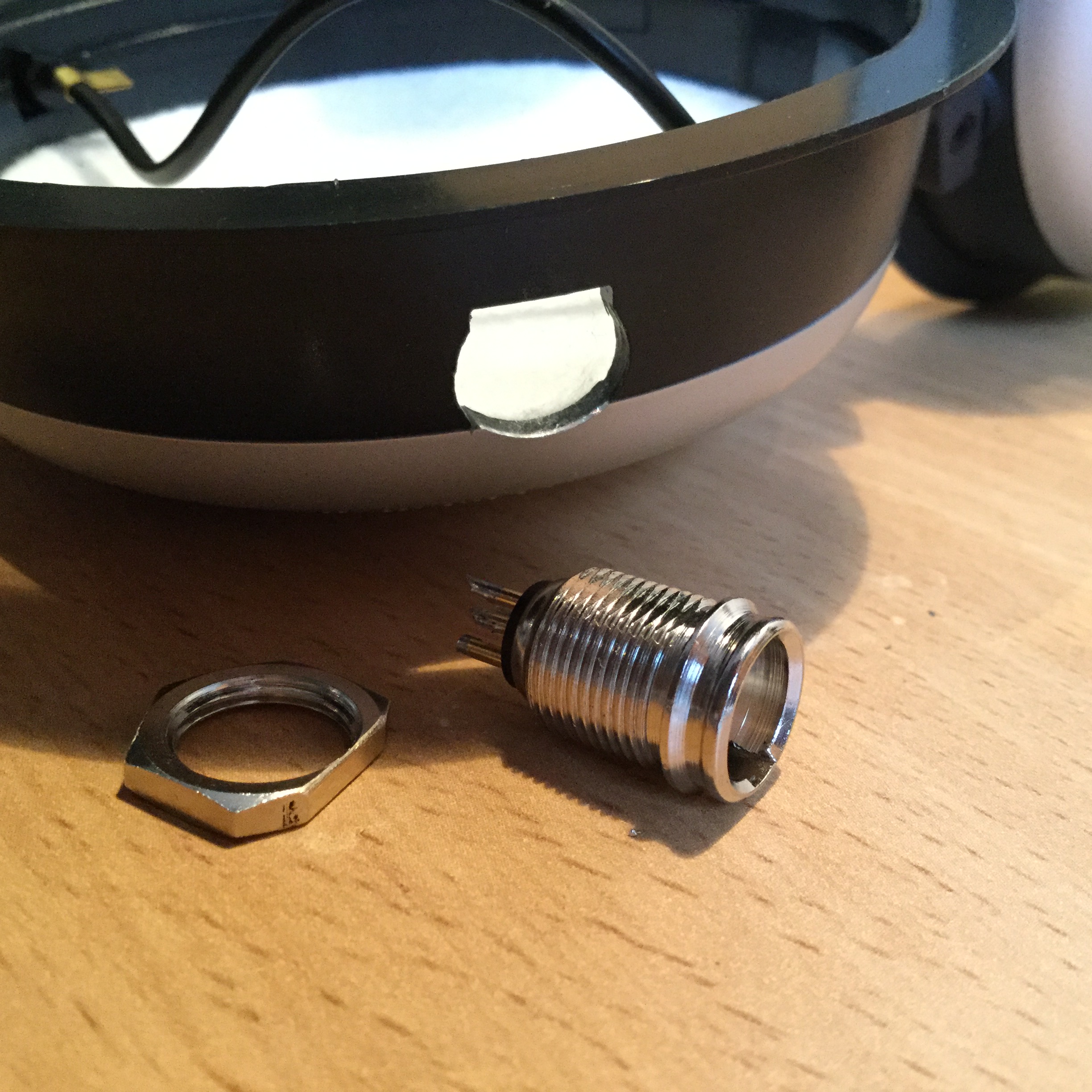
Once this is done you just have to solder your appropriate connector on(remember to slip the barrel on first or you may get annoyed) and you'll be all done.
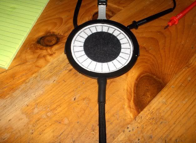
Finished Product
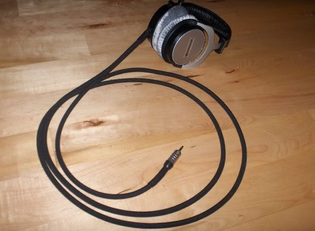
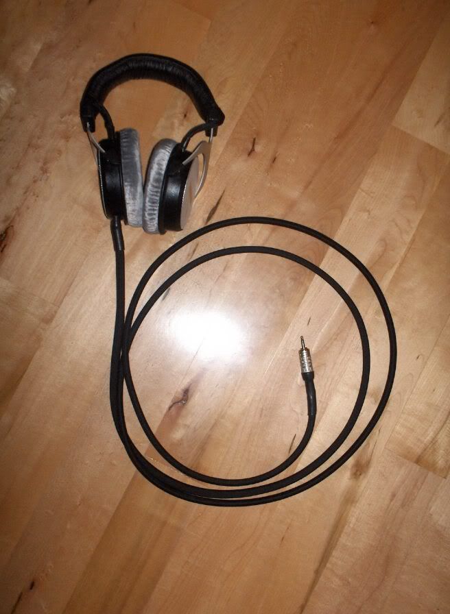
Beauty shots(thanks to kin0kin)


High-res Versions of desktop images
Thanks for reading my guide, feel free to comment or make suggestions.
[size=small]beyerdynamic DT880 Re-Cable[/size]
Tools/Materials
Soldering iron
Multi-meter
Appropriate wire(Mogami 2534 in my case)
Appropriate termination(Canare F12 in my case)
Heatshrink(optional)
Nylon covering(optional)
Heat Gun(optional)
Disassembly:
The first step in re-cabling the dt880s is to disassemble the headphones. This process should work for any of the 770/880/990 series beyer headphones.
1) Remove the velour ear pads.
2) Remove the padded headband. First you'll need to unbutton the fasteners and then it should come off easily.
3)Unscrew the tabs that say "DT880 L/R". You will need a philips screw driver for this. Remember to set the parts in a safe place. This allows us to work with the drivers separately from the headband.
4)Remove the driver. The best way to accomplish this is to use a small thin metal blade such as in a pocket knife. Simply wedge the blade in along the out circumferance of the driver and wiggle it a bit. The protective mesh should come out first and then the driver itself. Use caution here, replacing a driver could be expensive.
We now have the headphone disassembled and ready to start operating on.
The Wiring
One of the first things you'll notice upon exposing the dt880 drivers is that each driver has 3 terminals rather than the standard 2 terminals.
The center terminal is just used as a neat way to splice the signal cable for the opposite earcup and is used only on the left driver. In my case, I will use 4 conductor cable and will therefore be bypassing the center terminal on both drivers. To me, this way is less degrading to the signal.
For the above driver(left driver), terminal #1 is the positive connection, terminal#3 is the ground terminal and #2 will not be used by most people.
The red/gold mark on the driver indicates the positive terminal. On the right driver the terminals are opposite. This can be seen by the mark. This is something very important to watch for, don't assume both drivers have the positive terminal in the same position, look for the mark.
Here are both drivers completely desoldered from the stock cable(right driver is on the left side of the picture):
Now, after you completely remove the stock cable you will need to prepare your new cable. In my case, using Mogami wire here is my procedure: Strip the outer sheathing and shielding off two feet of the Mogami wire. Of the revealed wires there will be two blue and two white. Cut one of each color to a short length of about 6 inches and leave the other two wires uncut.
All 4 of the wires will enter the left earcup from the bottom. The two long wires take the extra journey from the left earcup to the right earcup. It is kind of important that the length of wire between the cups be approximately 16". This measurement works well with the headband so aim for that as a result. Once you get the 16" of separation you will have some extra cable in your right earcup. If you've got more than 5" or so of wire going into the right earcup you can go ahead and trim it down a little. Make sure that if you are adding heatshrink or anything to the connecting cable that you do it now before we start securing things.
Once you start getting your cables in place you may as well implement some strain relief. I like to use little zip ties. You want strain relief anywhere a cable leaves an enclosure.
After your cables are tied in you are ready to strip them and start soldering. I like to use the white/clear wires for signal (+) and the blue wires for ground (-). Remember my note on polarity and solder carefully.
Once your wires are soldered you need to do one little check. Strip a small amount of sheathing off the opposite end of your cable(where the connector will go). Use a multimeter or other method to determine which white wire is carrying the left signal and mark it somehow. The blues do not matter because they get tied together anyway. Marking the left makes it easier to solder on the connector without getting left and right backwards. Or you can just guess and then change it if it turns out backwards, your choice.
Finishing Up
Now you're gonna wanna do little odds and ends such as adding heatshrink, covering to the main cable. After this you start reassembly. Everything goes back together the same way it came apart, the headband assembly can be a little tricky. Try to route your connecting cable as neatly and evenly as possible, it should fit well if it's close to 16".
Once this is done you just have to solder your appropriate connector on(remember to slip the barrel on first or you may get annoyed) and you'll be all done.
Finished Product
Beauty shots(thanks to kin0kin)
High-res Versions of desktop images
Thanks for reading my guide, feel free to comment or make suggestions.


 ), if not, save yourself the time!
