Beta22 Designing Idea - Need your opinion.
Jan 17, 2010 at 4:51 PM Post #61 of 70
Quote:

Originally Posted by pila405 /img/forum/go_quote.gif
@Steve - Thank you very much again. Helpful as always.

Can you tell me please the exact products' name YOU used for the painting [primer/flat black/clearcoat]?

And what are the beta22 dimensions?

If I paint the aluminium, should it be anodized black or natural?
Do you suggest on any other material?
What do you think about professional electrostatic painting?

Does the Beta22 you have includes the O22 inside the same chassis?

@Koyaan I. Sqatsi - It will be great! Thank you very much!


1. I believe I just used Krylon primer, flat black and glossy clearcoat. I've also used Sherwin-Williams Duplicolor with decent results (self-etching primer, flat black, clear coat). To polish the clearcoat, I used 3M wet/dry sandpaper up to 2000 grit, rubbing compound and a rubber sanding block.

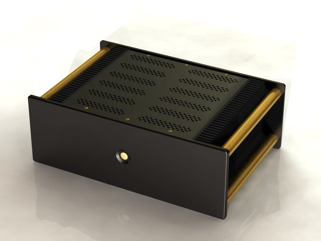
2. The dimensions are about 17" x 12" x 3" and the transformer and σ22 are both inside. I have virtually no hum after switching to a shielded transformer.

3. I'd recommend natural aluminum - it's light, inexpensive and relatively easy to work with.

4. By 'electrostatic painting' do you mean powder coating? It's worth looking into, since powder coating might be less expensive than painting (less steps involved). You can get glossy finishes but they tend to be heavily orange-peeled in appearance. You'd want bare aluminum if you were considering powder-coating.
 
Jan 17, 2010 at 4:59 PM Post #62 of 70
Quote:

Originally Posted by pila405 /img/forum/go_quote.gif
But all the idea is the clean look - no holes or huge heat sinks....
frown.gif


Maybe Helium cooling ^^'...


Aesthetics are nice, but I *strongly* recommend that you find a way to vent the case. You don't have to use a boring grid pattern for the holes - play around in AutoCAD. The holes don't have to detract from the aesthetics.

Here's how I'm venting my ß24, for example:
247-8-09.jpg


Poke around a hi-fi amplifier gallery for more examples of creative holes patterns.
 
Jan 17, 2010 at 5:18 PM Post #64 of 70
@Steve - thank you again for the detailed answer.
The chassis looks gorgeous!

I downloaded this AutoCAD inventor suite but I have no idea how to use it and I didn't find any tutorials on youtube [for newbs/beginners] :\.

@deathg0d - There won't be too much gap. The chassis will be made of aluminium. But if it will be closer it will dissipate the heat even better, no?

Aluminium dissipate heat better than air - isn't it?
 
Jan 18, 2010 at 3:17 AM Post #65 of 70
pila imo i think you got the idea wrongly. we are not talking about how to get rid of the heat from the mosfets.

the heat are being generated from the heatsinks, so there are serveral methods of 'getting rid of' that heat generated within the enclosure. one of the way is to have vent holes on top as the simple theory of 'hot air rises'

another method is to have a fan like a desktop to extract out the hot air with vent hole in the opposite direction for cooler air flow to be circulated in.

next will be having a chassis that conducts and dissipates heat very well for example aluminium and give minimal vent holes/gaps for air circulation, the whole chassis will act like a big 'heatsink'. hot air are both being taken away by the aluminium expose to the surrounding air and the gaps/holes for some air circulations plus if the room temp is low, it actually cools the aluminium and the hot air within, so i dont see that any damage will be done. generally all electronic components are build to MIL standards and will not fry under temp of 30-40 degrees. a very good example will be portable harddisk casing, i dont think we see any vent holes on it and these 2.5" babies run pretty hot as well.

the reasons i do not put vent holes especially on the top is that i have a bad experience of a a friend who was sweating heavily drop his sweat into my old amp while he was admiring from the top and short circuited the whole system. i believe all components will deteriorate after couple of years not because of heat but instead by wear and tear, like capacitors will becomes resistors cos it loses it charge etc. these are all my personal opinions and understandings so i am open to advises, cheers =)
 
Jan 18, 2010 at 12:12 PM Post #67 of 70
i have place a thermometer within my enclosure (tho this may sound silly) and i got some readings which are pretty close to my estimations from the start.
my b22 was running in balanced driving k702 in a room temp of 29 deg with 5% humidity after 2 hour.
the reading i got after 3 tries are 42.5, 43.2, 44.8. as the readings tell us that without vent holes the heat is not enough to cook/fry any components as i have did a reasearch on the smallest metal film resistor, their operational specs indicate that it will run from between -55 to 175 degrees.
i think from my readings, the heat generated are not even 1/3 of the resistor max temp plus a friend who helped me in building my b22 also told me that all components being used in the b22 are MIL standard and they can even operate under higher temp beyond the specs. he is working as a QC engineer for an electronic firm and his everyday tasks are to check and test failure rates of the company electronic products so i am pretty sure my unit will not failed due to heat.
 
Jan 18, 2010 at 1:40 PM Post #68 of 70
after 2+ hours of operations, i took my room temperature sensor and placed it into my enclosure and observed the readings for 30mins. the max temp it reach is 45 deg under aircon temp of 22 deg. i will give it a +5 deg max on a hot humid day here in singapore. so the conclusion is, 50 deg max is almost the operating temp of all electronic components
 
Jan 18, 2010 at 1:51 PM Post #69 of 70
Sounds great! What are your enclosure dimensions? [Height / depth / width / thickness of the aluminium] And what configure do you use? 4 channels balanced?
 

Users who are viewing this thread

Back
Top