


bazelio
500+ Head-Fier
- Joined
- Oct 29, 2015
- Posts
- 572
- Likes
- 115
Great thread! Currently considering the M11 to drive HD600s and at some point Beyer T1 Gen2s (don't own yet).
I've read several pages in this thread and I like what you guys are saying. The sound signature sounds like what I'd try to achieve in a R2R DAC / Tube Amp stack. Moljnir2 for example. Actually in the same price range, the Gung MB / Moljnir2 stack seems most appealing. It's probably asking too much for someone out there to have directly compared the this to the MB11 though.")
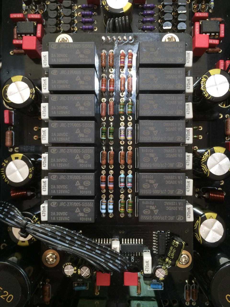
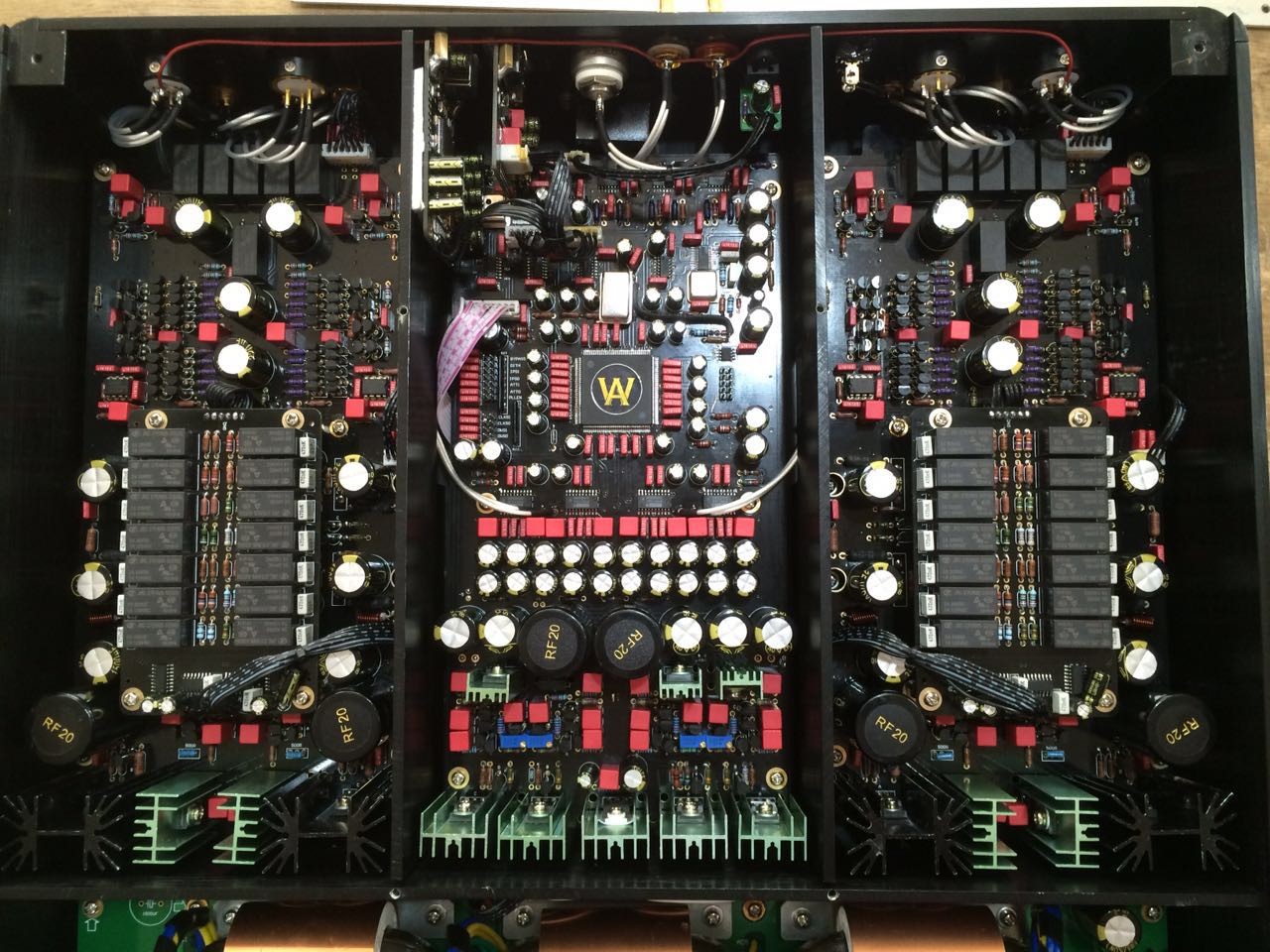
BTW, solder shorts on the FPGA pins sounds like a late workaround or bug fix. Very sketchy too. It'd be interesting to determine which pins and what their function is on the FPGA chip.
I've read several pages in this thread and I like what you guys are saying. The sound signature sounds like what I'd try to achieve in a R2R DAC / Tube Amp stack. Moljnir2 for example. Actually in the same price range, the Gung MB / Moljnir2 stack seems most appealing. It's probably asking too much for someone out there to have directly compared the this to the MB11 though.
BTW, solder shorts on the FPGA pins sounds like a late workaround or bug fix. Very sketchy too. It'd be interesting to determine which pins and what their function is on the FPGA chip.

