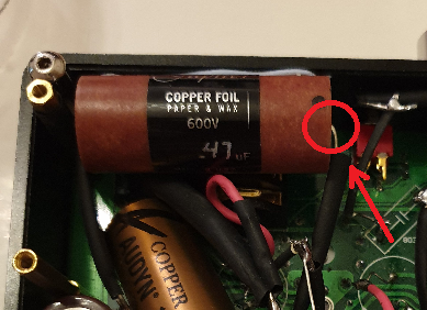
but why did they put a 200V capacitor there?
I have found and realized that manufacturers try to get away with whatever they have available to fit the job.
Most likely either the shipment of that spec cap was cheaper, or they are using cap for more than one location, so it work out cheaper for ordering parts if yoh can get away with whatever you already have...
The only thing concerning me was whether I have lost any higher frequency response due to not using bypass caps but I don't think I have and I won't be able to check properly until I can compare it with my headphone amp which is currently out of order.
The increase in Cathode cap is to stabilize that voltage drop for bass sustain and bass punch,
Which is optimized with larger Cathode Electrolytic value of 1000uf.
This is due to the "larger" cathode cap value causing the effect of holding the cathode voltage constant, in relation to current demands,
So the tube is kept at optimal gain.
Also, at such large capacitance of 1000uf, it should compensate for any performance or noise issues of the combo of Q2&IC3 wich, as "pvico" noted, are china parts which s
et the tube bias at 25ma.
Most good electrolytic caps perform similarly,
but the one we used is the "Audio Note KAISEI",
Which is supposed to be the best as it closest to the "blackgate" caps,
which were highly regarded but not made anymore.
So Audio Note Kasie caps are recommended first, then Panasonic or Elna silmic2.
")
Anyways, adding the second paralleled cathode cap(bypass) is for:
Quoted from member "Ridge78" :
"Bypass : in order to help the Lytic cap in the areas it is weakest (treble, microdynamics, ...), we add in parallel an another cap of a different techno, smaller and faster."
Since the KAISEI caps are already good enough,
my reason for adding bypass was to offset any tonality changes of the Cathode cap (KAISEI, have a slight darker tonality) compared to the coupling cap.
So my coupling cap and bypass cap are same exact brand & model.
But just using the Audio Note KAISEI is just fine as it is "supposed"
to be the best..
I editing this post a year later because I have tried various caps since in different amps and in these types of circuits where there's a cathode cap, it will play a factor to the sound, and Kaisei caps in tbis situation will provide a darker richer tonality, while a Nichion KZ will be more neutral, and I prefer them over any Silmic2.
Remember the caps are in a situation to affect tonality
only because they are in a position of being a "cathode cap".