Another amp layout to check
Jun 6, 2006 at 10:54 AM Post #31 of 37
Quote:

Originally Posted by threepointone
hmmm. . .not anymore, it seems
icon10.gif
mouser has ~700 stock of the buf634p and another 600 on order in a couple of months.

diamond buffered is still nicer though
icon10.gif


I haven't checked in awhile, so that's nice to know. TI's site had been saying that >10K were due sometime in June.

As you say, though - everyone says DB is the ultimate. Nate has actually plugged a MH DB board into the BUF sockets on a PIMETA, but I think it was a pretty creative effort.
rolleyes.gif
 
Jun 8, 2006 at 2:38 PM Post #32 of 37
Quote:

Originally Posted by tomb
Cetoole,
How's this design coming? Everyone's salivating over whichever latest SMD MINT/PINT comes through, but I thought a Diamond Buffer version of the PIMETA was a great idea. Some of us are still looking for a through-hole project that's still about iPod size or thereabouts, and offers a little more choice than the tough-to-get BUF634.


Not really any updates on this recently, I have been working more on the tiny smd version. I have changed just a couple very minor items, and I am kinda tempted now to go back and replace the lone jfets biasing the buffers with cascodes, shouldnt need to increase size, and should give superior performance.
Quote:

Originally Posted by tomb
As you say, though - everyone says DB is the ultimate. Nate has actually plugged a MH DB board into the BUF sockets on a PIMETA, but I think it was a pretty creative effort.
rolleyes.gif


That DB is much more complex than mine, it could probably fit though in SMD, but many people here dont seem to like SMD, for some strange reason. As to Nate fitting that buffer in a Pimeta, we all know Nate is crazy (Just kidding, you know we all love ya Nate), and I cant imagine the contortions needed to get it to work.
 
Jun 8, 2006 at 7:18 PM Post #33 of 37
Ok, a bit of an update here, minor changes to the layout to accomodate the changes in the schematic, namely all ccs jfets are now cascoded, and have source resistors.
pimetadblay3.png

pimetadbsch3.png
 
Nov 2, 2006 at 12:34 AM Post #34 of 37
Little wakeup for this.

I'm not positive on all the part numbers and values, here's what I figured (and got) for the latest schematic, please correct me if I'm wrong:

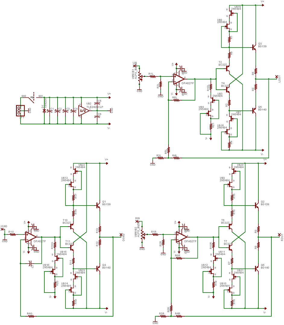
Please note right away that I will be using 2N5486 instead of 2N5484 which are rated at somewhat higher current. This is the diamond buffer:


The main thing is the 1K value of the source resistor R1/R4, R15/R16, R17/R18 - (same thing, different channel). I'm not positive if this is the correct value, but I'm thinking it is.

Also, for Class-A biasing of the opamp, I'll be using 1K for R10 (R10G, R10R & R10L) and most likely leaving the source resistor at 1K as well. Again, I'm kind of guessing here since I'm not positive on how to find the exact value of it.

Now, on to the parts list:
Power section

D1 : 1N4004
C1-C4 : Panasonic FM 560uF/35V
TLE : TLE2426ILP
C5-C6 : 4.7uF/63V Polyester Film

Diamond Buffers

PNP Input Transistors (T2, T6, T10) : BC327
NPN Input Transistors (T4, T7, T11) : BC337
PNP Output Transistors (Q5, Q6, Q4) : BD140
NPN Output Transistors (Q3, Q2, Q1) : BD139
CCS Transistors : 2N5458 & 2N5486
CCS Source Resistors (R1, R4, R15, R16, R17, R18) : 1K Will be testing stuff until I get ~ 8mA out of the CCS
Output Emitter Resistors : 4.7Ohm
Input Emitter Resistors : 10Ohm This will make the output current = CCS current x 2.1, looking for 15mA of output current - not sure why yet
smily_headphones1.gif


Amplifier / Ground
Class-A CCS Source Resistors (R19, R20, R21) : 1K Will be trying to Class-A bias the opamps to 5mA - hope that works well with OPA637s
Class-A Transistors : 2N5458 & 2N5486
R10G, R10R & R10L : 1K

R1R, R1L & R1G: 4.42K
R2R, R2L : 1M
R3R, R3L : 1K
R4R, R4L : 10K
R4G : 4.42K
R5R, R5L : Definitly SOCKET to tweak gain: Stock will be 3.32K for gain of 11.
R6R, R6L : 470K

C7 : 10pF C0G/NP0 Ceramic
Caps around OpAmps: 0.1uF X7R Ceramic

OPAMPS: Here, I'm trying out the OPA637/OPA627 for the first time
smily_headphones1.gif
So for OPA637, gain will be pretty high, I'm thinking stock Pimeta gain of 11x. I'll socket one place to drop gain to 6 or 8 if it's stable, if not, I'll keep it at 11.
 
Nov 9, 2006 at 8:09 PM Post #35 of 37
Updated some values on this design, will be starting it very soon.

Last minute questions
1) Class-A Bias for Ground channel - should it be the same as Left/Right? I'm using OPA637/OPA627.
2) Class-A Bias for OpAmps - I'm thinking 5mA.
3) CCS for Diamond Buffers - I'm thinking ~ 7-8mA CCS for output current of 15mA with 10R input resistors and 4.7R output resistors.

Any help would be appreciated, after reading so much stuff on diamond buffers, my head is up in the clouds trying to sort all this stuff out.
 
Nov 10, 2006 at 4:17 AM Post #36 of 37
I would be able to build right away and infact make a single layer version myself to test if you think the design is good. I currently stock all the parts right now.

For help with Diamond buffers, have you looked at this topology yet?
dDB_isb_v022_schem.jpg


This is a design from Phil Larocco (aka PPL) what was used for the Diamond buffer in the Millet Hybrid. I guess this worked out really well and is also a variation of the PPAv2 Buffer that seems to work very well. As for the Transistors, any reason for going with BC327/337 instead of 2n5087/88?
 
Nov 10, 2006 at 2:46 PM Post #37 of 37
Tedro: Yup, I've seen that diamond buffer design and heard quite a bit of good stuff about it, but I was a little more interested in the one I had posted because I had breadboard layouts ready for those and have done them before with great results (just finished something which could be basically called a PINT with a simpler power supply and diamond buffers - sorry, no pics since I just built it for someone else, that and quite a few Sijosae Class-AB amps which use his Class-AB buffers which again sound pretty good).
As for the BC327/BC337 transistors, I simply chose them because I was using them for the Sijosae Class-AB amps and had some left.

I started the amp last night, but since this is a little bigger than any other amp I did on breadboard, it might be a little slow to finish.

I was testing Idss of all of my transistors last night and got these values:
2N5486 : 40 peices, all 14-16mA
2N5458 : 15 peices ~ 2.5mA, 15 peices 4.5-6mA

After testing the Idss in pairs with a source resistor, I realized that I get very low Idss out of the whole circuit unless I'm using a very low resistor and the highest 2N5486/2N5458 pairs. With a 16mA 2N5486, a 6mA 2N5458 and a 500Ohm resistor, I'm getting less than 4mA of current.
How much current should I be looking for on the CCS?
 

Users who are viewing this thread

Back
Top