Quote:
Originally Posted by mono
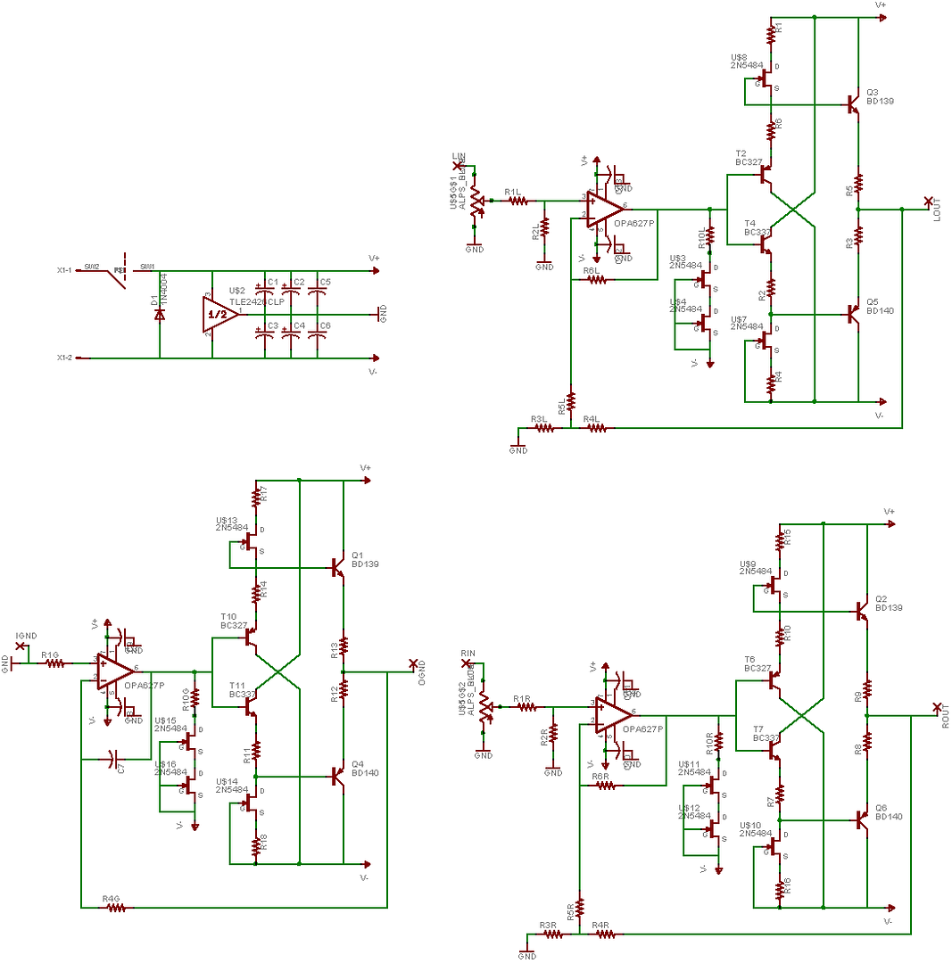
You might consider moving from 2N5484 to 2N5485 or 86, since the resistor will allow reducing CCS with any of them, but some people might want it higher than a random sample of 2N5484 would allow.
As it stands, there should be no need for TO220 output parts or heatsinks, they just wouldn't build up much heat at the max possible 5mA CCS of 2N5484.
What might be nice is if the board had a divider, with a Tread-like supply and/or a dual supply (if to appease those who want to avoid the TLE2426 for some reason). That part of the board could be scored and snapped off if the builder didn't want it integrated, and the supply tracks from it to the other board used jumpers so if the board were scored and broken, it didn't leave traces going to the separated board edges.
Another idea would be to allow for paralleled BD139/140, at least a 2nd of each.
I also like the idea of rotating the pot 90', and maybe putting a 1/4" HP jack at the opposite end of the board. Of course not everyone would like this but I get on this kick to reduce wires...
I would like the board files for this, please. I don't know if I have time to get anything done, but I like it already and given all the input it may receive and the early stage, it might change more than I'd want, I might like it better as it is now. I had already planned on doing a derivative of PPL's Lisa2 and your design incorporates some of the changes I'd considered.
|
I thought the 2N5484 and 2N5486 were both the same pinouts, just having different range of IDSS values. Unless that is not the case, I dont see what the problem is. I have eagle parts libraries for the 2N5484, and not the 2N5486, which is why you see that part on the board.
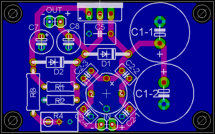
As for integrated dual PS, I dont personally see the need to have it integrated on board, especially with jumpers required to utilize it. It is an interesting idea, though requires more work for the builder. I have done a layout recently for the tread (Tangent comes up with such great schematics, I cant help myself. Thanks Tangent
), and it wouldnt be difficult to integrate a pair of these replacing the TLE2426.
I dont really like the idea of paralleled output buffers; I would think the TO220 package would be able to dissipate enough heat that class A wouldnt be an issue with most of the headphones used. Three of the output transistors now have enough space to allow the use of small heatsinks, and it should be simple to add enough space for the others, I am just not sure if its needed.
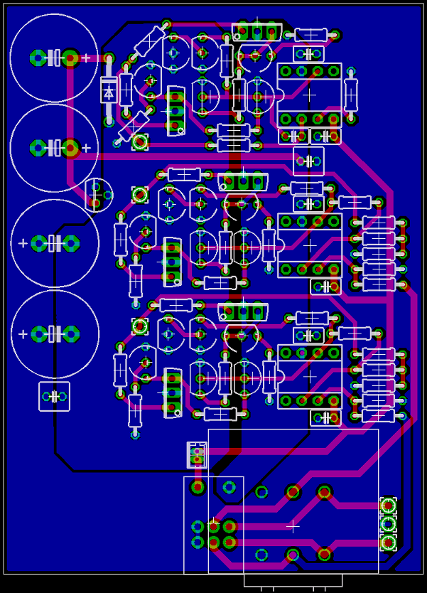
See that space next to the pot? That space used to hold a board mounted neutrik combo jack, which is, IMO, one of the nicer jacks of the sort I have seen so far. The main reasons I scrapped that were flexability, and it greatly complicated the trace layout. Unfortunatly, with the pots I like to use, the amp would be just a bit too tall to fit the Hammond 1455L1201, and mounted sideways, the next case that would fit is the 1455N1201, which is much taller than we need. It would give space though for the dual treads you were talking about earlier, and I cant find any other cases that I like more, so I will think about it. If you want the board files, just shoot me a PM with your email address or some way to send the files.