Altec Lansing iM716 Predicament
Dec 31, 2007 at 10:55 PM Thread Starter Post #1 of 31

khbaur330162

Vintage Ortho Ninja 🥷
Joined
Aug 5, 2006
Posts
2,010
Likes
1,825
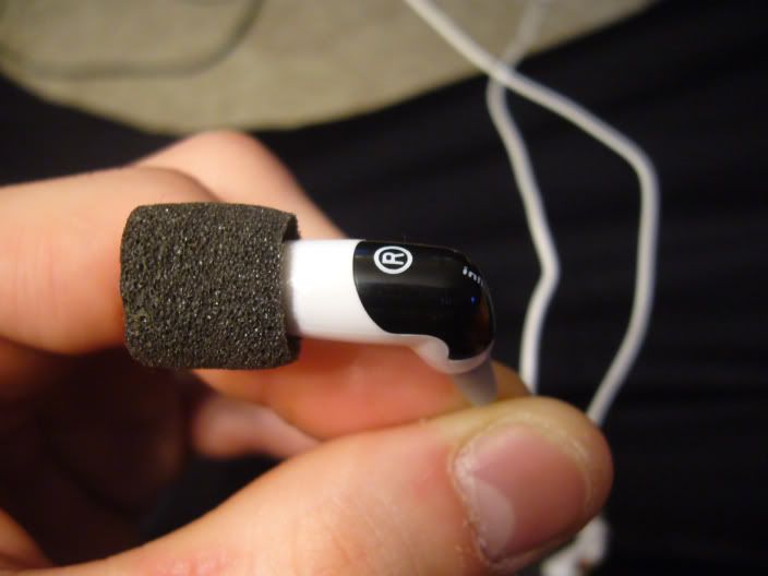
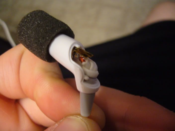
Has anyone actually opened the driver housing on their iM716's? I did for both my iM716 and iM616 and they have a single tiny surface mount resistor for each channel. I'm not really sure what they are even for.

I bought some 75 ohm resistors for the podectomy, going a little high in value due to my plan of simply removing the entire mini PCB for the sake of a recable, however, I'm now having second thoughts. Does anyone think removing these resistors could have a negative effect on sound quality?

Here's a few pictures of the internals, along with a quick diagram I drew because it's a little hard to see what's going on with everything being so tiny.

P1050430.jpg

P1050433.jpg

P1050437.jpg

P1050446.jpg


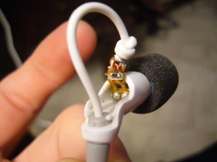
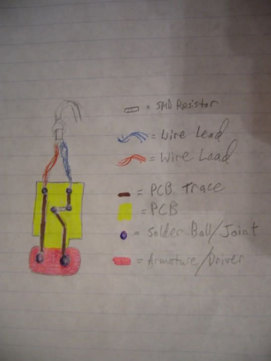
On the resistor itself is the number "0" printed in white lettering for the iM716's left channel, and "000" for the right. For the iM616 it's "180" for both.
confused.gif
 
Dec 31, 2007 at 11:24 PM Post #2 of 31
I think the D1 on the board would indicate that it's diode rather than a resistor. Do you have a DMM? If so you can just check to see if it is infact a resistor by checking the resistance.
 
Dec 31, 2007 at 11:41 PM Post #4 of 31
Quote:

Originally Posted by firefox360 /img/forum/go_quote.gif
I think the D1 on the board would indicate that it's diode rather than a resistor. Do you have a DMM? If so you can just check to see if it is infact a resistor by checking the resistance.


Nope, I don't have any type of volt or ohmmeter. It's a little difficult to even see in person due to smearing, but on the iM616 you can see definite legs on the "D" which leads me to believe it should read "R1."

Even if it was a diode, what would you imagine its purpose would be?

Quote:

Originally Posted by DanT /img/forum/go_quote.gif
How do you open the earphone casing without braking anything? It might be interesting for those who want to recable.


That's exactly what I'm attempting to do. I've bought some 75 ohm, metal film, 1% tolerance resistors to be soldered inline with some 26AWG SPC cabling. I hope to drastically increase the sonic performance of these IEM's, and as you can see, make 'em a lil more aesthetically appealing. The Zebra effect looks nice on both iMx16's.
smily_headphones1.gif


I take no responsibility if you break anything while attempting to mod your IEM's:

I took a paper clip and slid it carefully up the side of the rubber sleeving. After discovering no driver/internal wiring was in the way (I could hear metal tapping on plastic), I applied a fair amount of force underneath the top plastic piece via the paper clip to detach it from the housing. The iM616 was much easier due to the fact that the iM716 had some type of glue holding it shut, whereas my 616 did not. It doesn't look like I damaged the plastic pieces in any way, however, they don't stay on nearly as well as they used to. (I can easily take them off with my fingers now) I plan to hot glue them shut after completing all modifications. Please, only attempt if you feel competent with DIY.


I plan to take pictures along with detailed notes concerning exactly what I'll be doing throughout the modification process. I also am saving funds for some custom ear molds by HearYourself.com. Stay tuned.
 
Jan 1, 2008 at 5:48 AM Post #6 of 31
Oh so tiny. When undergoing a podectomy I was having problems with the solder not sticking andflowing. It was forming peaks. What is the reason for this?
 
Jan 1, 2008 at 7:17 AM Post #7 of 31
Quote:

Originally Posted by swt61 /img/forum/go_quote.gif
Wow! Matt you're always breaking new ground with IEMs. Those wires are so small, that would be a bear to solder. I'll stay tuned, pretty cool stuff!


Well, I do try and thanks, Steve! I know I at least have some support!
wink.gif


I ordered some Cardas quad eutectic solder and a brand new temperature control soldering station to help me with the modding process. I really hope I can pull it off, and I'm sure the sound will pay me back "in spades" if I'm successful.

I still have some of those old custom ear impressions made with the epoxy putty from my last IEM adventure. I'm gonna see if I can get my arse over to Ace Hardware or Home Depot to either get some of that rubber dipping material konish talked about, if you remember the old thread, or some regular old epoxy. I sort of gave up on the DIY custom ear molds due to money issues, but I'm thinking I might be able to finish what I started. This will be a project to keep me busy, indeed!
eek.gif


Quote:

Originally Posted by Gino /img/forum/go_quote.gif
Oh so tiny. When undergoing a podectomy I was having problems with the solder not sticking andflowing. It was forming peaks. What is the reason for this?


Did you tin the wires prior to attempting to solder them to any type of joint? Tinning wires and a properly heated iron are key elements to succeeding in the game of DIY audio. Also, keep a damp sponge nearby to keep your iron's tip clean of resin and other dirties that might stick to it. Keep in mind, too, that the stock Altec Lansing cable is coated with a dielectric so as to keep the signal from shorting. You might need to scrape some of this off if you can't get a clean contact for soldering.


So does anyone have an inkling as to what that diode/resistor could be used for, or whether or not I could remove it w/o possible damage to the iM716? I think I might just solder the cable to the PCB and forget about it completely, but I thought a true audiophile would attempt to get as clean a signal to the driver as possible, which would include removing any consumer grade electrical components from my amp's direct signal.
frown.gif
 
Jan 1, 2008 at 8:14 AM Post #8 of 31
Hmmm, another potential mod. I guess Altec, in agreement with Etymotic took all means to make their IEMs a bit inferior to the ER4. Or perhaps a a focused group discussion preferred less analytical buds.
 
Jan 1, 2008 at 6:45 PM Post #9 of 31
Quote:

Originally Posted by Gino /img/forum/go_quote.gif
Hmmm, another potential mod. I guess Altec, in agreement with Etymotic took all means to make their IEMs a bit inferior to the ER4. Or perhaps a a focused group discussion preferred less analytical buds.


After I hot glue the housings shut it'll be difficult to remod, however. I'd like to get everything done first time around. So if I can completely remove the PCB, GREAT! If I can't, sort of sucks, but at least I'm up a working pair of headphones.

If anyone has ANY type of educated guess, please spit out recommendations as to what I should or could do. It'd be much appreciated.
 
Jan 1, 2008 at 6:49 PM Post #10 of 31
Wow, this is quite surprising. I remember the iM716 are only 5ohms without the Pod.. Maybe somebody can open up their iM716 and see if the D1 is indeed a resistor.
 
Jan 1, 2008 at 6:56 PM Post #11 of 31
Quote:

Originally Posted by khbaur330162 /img/forum/go_quote.gif
After I hot glue the housings shut it'll be difficult to remod, however. I'd like to get everything done first time around. So if I can completely remove the PCB, GREAT! If I can't, sort of sucks, but at least I'm up a working pair of headphones.

If anyone has ANY type of educated guess, please spit out recommendations as to what I should or could do. It'd be much appreciated.


My guess is it is unlikely that D1 is a resistor considering the drivers are only 5ohms with a Pod and I doubt anyone would name a resistor placing "D".

You probably should try to find out if what the D1 is before removing it. A simple check if it is a diode would be connecting a LED to a 1.5V battery and use the leads to test on the D1. Diodes are only 1 way.

Be carefut though, 1.5 volts can KILL your driver
biggrin.gif
 
Jan 1, 2008 at 6:56 PM Post #12 of 31
I recabled my iM716s back when I still had them, but I just attached the new cable to the flex PCB in the housing, I didn't remove or bypass it. It didn't really have any negative effects on sound quality that I recall but I did need to add some resistors to get them back to where they were. They were far too easy to drive without the resistors in line on the cable. I'm afraid I don't have any pictures of the internal, probably for the best since it was my first recable and not a high quality one, plus the in-line resistors were an afterthought and they definitely looked like it. I can dig up some pictures of the finished product but I doubt that would help much.

Found it. Link to the picture. I wish I had spent more time on them to make the resistors look decent. I wish I had kept them actually, I've finally found a use for them.
 
Jan 1, 2008 at 7:21 PM Post #13 of 31
Jon118: Hey, that's not a bad looking recable... It looks almost like you used the iM616 cable to simply get rid of the pod, and then you attached some inline resistors. Is this the case?

I'll be attempting to solder the resistors a little closer to the termination, but my cabling will have to be braided so mine might end up looking even slightly more amateurish. Yet, much like it was for you, this will be my first attempt at a recable.

ezzo: Yea, I've got 75 ohm resistors on their way to me now to ensure tolerable impedance. I won't attempt to test this mystery component w/o proper tools, however.
 
Jan 1, 2008 at 7:39 PM Post #14 of 31
Actually the cable is from the Zune earbuds, and I assure you the resistors look worse in person. They're easy enough to recable though. I'm not sure if the flex PCB is necessary, but I seem to remember the ER-6s having one as well, so that's why it didn't cross my mind to try without. But basically I did recable with the Zune earbud cable then cut it around the y-split and added in line resistors yes. I think for portabilities sake it would be nice to have them in the plug if it's big enough, with the the resistors and plug I was using I didn't have enough room, plus for the first time it would probably be easier to put them outside.
 
Feb 15, 2008 at 9:27 AM Post #15 of 31
Quote:

Originally Posted by khbaur330162 /img/forum/go_quote.gif
After I hot glue the housings shut it'll be difficult to remod, however. I'd like to get everything done first time around. So if I can completely remove the PCB, GREAT! If I can't, sort of sucks, but at least I'm up a working pair of headphones.

If anyone has ANY type of educated guess, please spit out recommendations as to what I should or could do. It'd be much appreciated.


I wonder if Loctite or a nail polish clear coat won't keep it in place but still give you an opportunity to snap it off again, if need be
 

Users who are viewing this thread

Back
Top