Altec Lansing iM716 Predicament
Feb 18, 2008 at 3:16 PM Post #16 of 31
Hot glue is fine. If used sparingly, it will be easy enough remove.

My cable broke tonight to my dismay. Small cracks developed on the insulator near the plug strain relief. As a temporary remedy, I applied clear epoxy around the area. It works fine now.

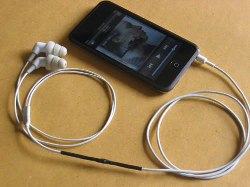
I am now looking to recable my IM716. My iPod Touch buds seems to have the right size and color cable to replace the plug to pod segment. The cables running to the buds are very thin. Looks like I may have to look for cheap buds with white cables.
 
Feb 27, 2008 at 6:56 AM Post #18 of 31
I recabled using the Apple oem cable. Sound good. I just had trouble when the tracings broke from bending. I scratched a bit of it and soldered. I hope it holds.

recable.jpg
 
Aug 13, 2008 at 9:55 AM Post #19 of 31
Quote:

Originally Posted by firefox360 /img/forum/go_quote.gif
I think the D1 on the board would indicate that it's diode rather than a resistor. Do you have a DMM? If so you can just check to see if it is infact a resistor by checking the resistance.


Its a resistor, ~0.5 ohms. It actually says R1, not D1, on the board. A diode would make no sense.
 
Aug 13, 2008 at 7:30 PM Post #20 of 31
Is there a higher end model with a higher resistance? It may be the case that the PCBs are used across different model(s) [regardless of the driver] and to save the trouble of creating two different PCBs, they just created a ton of the same one(s) and decided to solder an SMD jumper (000/0 ohms) in the place where another resistor (75 ohm) would have gone in a different model.

Maybe it's similar to ety ER4 P <--> S adapter. (i.e. resistor built into the headphone).

D1 makes no sense, anyways. It's gotta be an R1, IMO.
 
Sep 29, 2008 at 6:35 PM Post #21 of 31
Quote:

Originally Posted by diredesire /img/forum/go_quote.gif
Is there a higher end model with a higher resistance? It may be the case that the PCBs are used across different model(s) [regardless of the driver] and to save the trouble of creating two different PCBs, they just created a ton of the same one(s) and decided to solder an SMD jumper (000/0 ohms) in the place where another resistor (75 ohm) would have gone in a different model.

Maybe it's similar to ety ER4 P <--> S adapter. (i.e. resistor built into the headphone).

D1 makes no sense, anyways. It's gotta be an R1, IMO.


Sorry to bring this old thread back to life, but I can confirm that this is absolutely correct. Adding 0 Ohm resistors where you might want to change something in the future is common practice. (If you only knew how many of these little fellows I've soldered...)

If you read the first post you'll see that the iM616 comes with "180" (18 Ohms, I suppose) resistors. The iM716 has its resistors in the pod instead. I suspect this is the only significant difference between the models... I'm planning to mod my iM716 when they arrive (bought them cheap because of defective cable) with around 56 Ohm SMD resistors (or regular if they fit). Hopefully I won't destroy the pads.
wink.gif
 
Sep 30, 2008 at 4:15 PM Post #22 of 31
interesting, i should have done this instead of keeping the pod and putting thru hole resistors there.

as for Diodes not making sense, doesn't ultrasone put diodes in their headphones? i don't really remember the reasoning behind it either as these are AC signals..
 
Oct 9, 2008 at 4:33 PM Post #23 of 31
OK so i just recabled the iM716. I found two ~70 Ohm's inside the pod, so I switched the 0 Ohm ones with those, and soldered new cables (I assumed higher added resistance wouldn't matter, because I remember Don Wilson writing somewhere that adding more resistance to the ER-4P than 75 Ohm wouldn't make a difference sound-wise). Then I superglued everything shut. The looks could be better because I had to put some glue on the outside, but I'm shinking of adding some red and blue heat shrink which will cover that up. It doesn't matter much though -- if they can spot the glue, they they're probably TOO CLOSE. I'd rate this a HUGE SUCCESS considering I didn't manage to break the small SMD resistors when removing them. I would NOT recommend this to people wihtout experience in SMD soldering. Then it's probably better to just attach the wires (pretty easy) and then putting the resistors somewhere in the cable or in the jack.

I also found a little clip thing from an ID card holder which fit perfectly on the rubber piece where the cables split.

I didn't take any pictures from the inside, because such picturs have already been posted. However, here's the finished product:
20rtsv4.jpg


Oh, and they sound fantastic. I honestly can't say they sound better or worse than my ER-4S. Veeeeery close sound signature. I should get those comply tips for my etymotics as well as the tri-flanges make my ears hurt after 2-3 hours. From now on I'll probably use these out on the street and keep my etys for listening at home.
 
Jan 12, 2011 at 6:55 AM Post #27 of 31
i just recabled my im716 and now playing with the resistors..

 
now i wanna ask a question
 
let say i intend to put 33ohm in each channel..is there any significant sound difference between using 2 & 75ohm(paralleled) resistors and 50 & 100ohm (paralleled as well)? if you calculate and obtain the total impedance of both options, the value should be similar, 33ohm..
 
Jan 12, 2011 at 8:15 AM Post #28 of 31


Quote:
i just recabled my im716 and now playing with the resistors..
 
 
now i wanna ask a question
 
let say i intend to put 33ohm in each channel..is there any significant sound difference between using 2 & 75ohm(paralleled) resistors and 50 & 100ohm (paralleled as well)? if you calculate and obtain the total impedance of both options, the value should be similar, 33ohm..


It may seem like you add two resistors in parallel and the resulting total resistance is half the original value - but that's not the case.  It only works out that way when both resistors are the same.  Parallel resistances are totaled by adding their reciprocals and taking the reciprocal of the result.
 
Paralleling 2R and 75R results in: 1/2 + 1/75 = 1/Rtotal or 0.5 + 0.0133 = 1/Rtot, and so 1/Rtot = 0.5133.  Then Rtot = 1.95 ohms.
 
Paralleling 50R and 100R results in: 1/50 + 1/100 = 1/Rtotal or 0.02 + 0.01 = 1/Rtot, and so 1/Rtot = 0.03.  Then Rtot = 33.3 ohms.
 
If you typed that wrong and meant two 75R resistors, then:
1/75 + 1/75 = 1/Rtotal or 0.0133 + 0.133 = 1/Rtot, and so 1/Rtot = 0.0266.  Then Rtot = 37.5 ohms. (without roundoff) 
 
As you can see, a different answer each time.
wink.gif


Jan 12, 2011 at 12:08 PM Post #30 of 31


Quote:
oh sorry, misstypo!!..i meant two 75ohm resistors..the resulting impedance as you already calculated is 37.5. while paralleling 50ohm and 100ohm resistors will give you 33.3ohm.
 
now that you know the real question, can you enlighten me with some thoughts?


All resistors add a bit of noise, so less is better.  I'd buy the correct size, period, and forget about paralleling.  Plus, I've read the entire IM716 Podectomy thread (I have a pair, too) and I thought the general consensus was 47 ohm, not 33.


Users who are viewing this thread

Back
Top