


scootermafia
MOT: Double Helix Cables
- Joined
- Nov 24, 2008
- Posts
- 3,025
- Likes
- 246
Everybody knows and loves it, right? Head-fi is certainly in a bit of a flap about the new Lightning plug, as is the rest of the world, since it's a big departure. I've got a few Lightning cables on hand so the point of this thread is to be a permanent source of information on this plug since curiosity abounds.
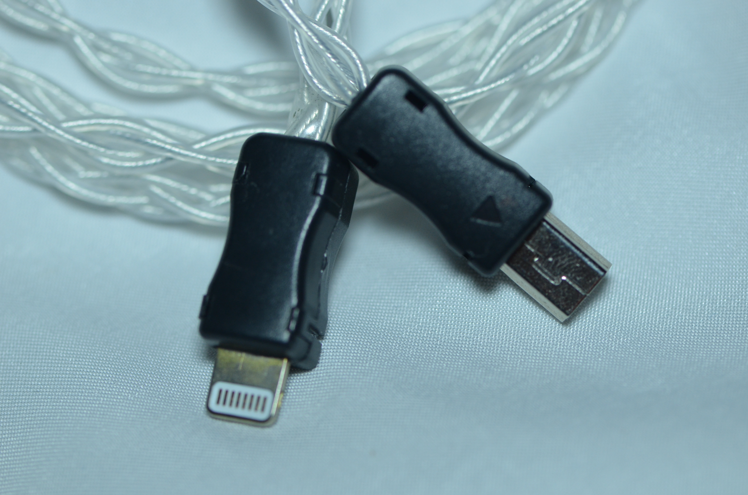
Pix (sorry for the crap quality):
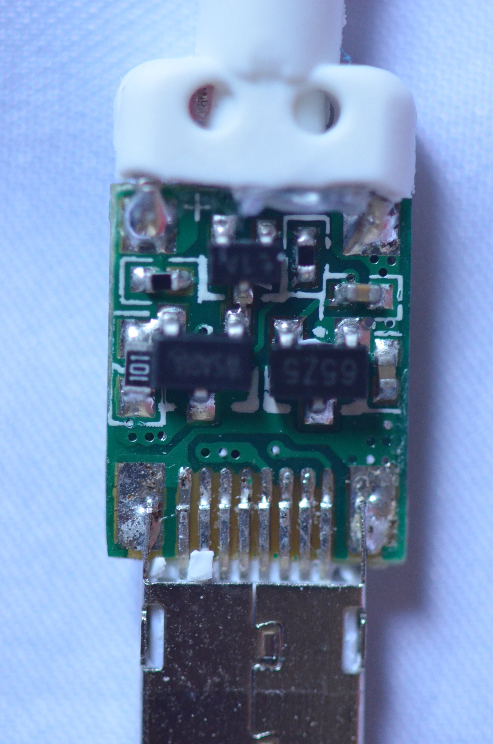
UPDATE: The person has authentication chips in it. Keep in mind this is super small, and magnified with a 1:1 macro lens...


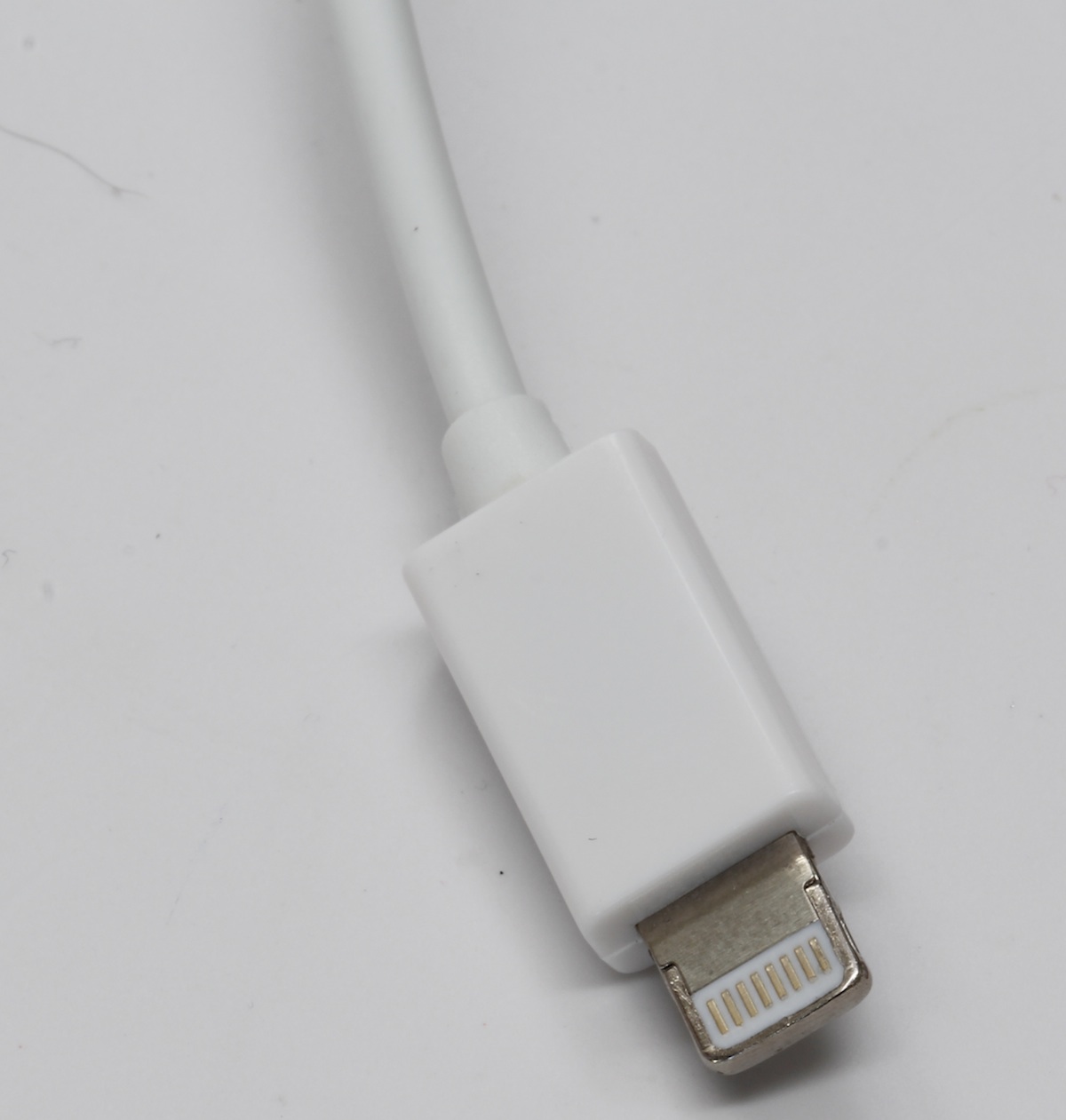
2 of the standard cables from Apple arrived today. First thing I noticed is that the Lightning plugs are SMALL. Pinky fingernail size. The contact points on the plug are so tiny, it is hard to probe them with a multimeter. Also, they are tough and look really good. This is not a cable that is going to break easily. It is a fraction of the width of a dock plug and isn't going to snap off or have weird problems with locking, and so on.
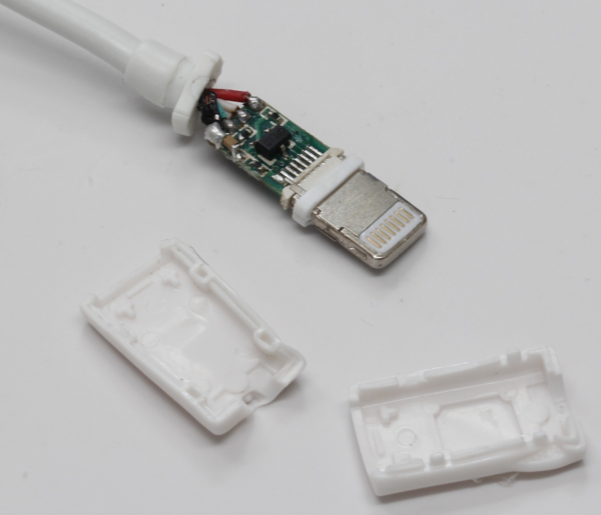
Removing the plastic shell around the plug reveals a two piece metal crimp surrounding the solder area of the plug, as well as some injected silicone rubber cushioning. This plug is built like a tank, it is armored. Modders are going to want to give up on the idea of building their own charge cables/CLAS cables from scratch for this, until a DIY version of this plug surfaces. I don't expect a DIY version of this plug will go for that much, despite how pretty they are, since at wholesale you can get a healthy discount on these cables. The amount of force required to remove the crimp is insane, it is really on there. I got it off without completely destroying the plug, and was greeted with a generous coating of epoxy. Scraping all that off reveals a tiny PCB with the 4 wires of the USB cable connected to it. The PCB extends into the end of the cable, where I'm guessing the traces split off and cross to allow the two-sideness of the connector.
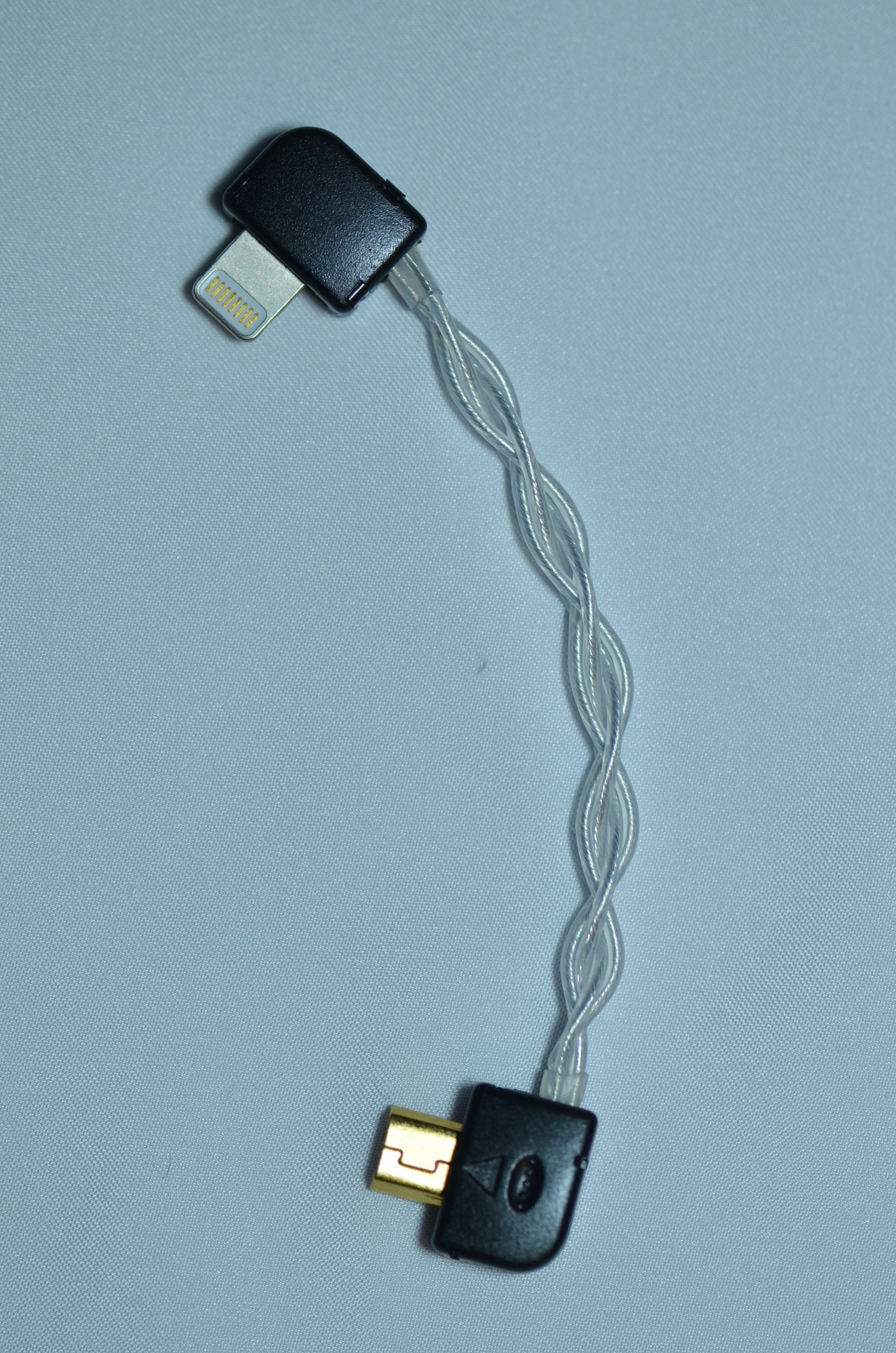
For modders, we have a tiny ~32awg pair of green and white wires which are for data. I'll post the exact specs when I get home. There is a 26awg red power wire for V+. V- duties are done by the cable's shield, which has several easily accessible drain wires for soldering to the plug of your choice. It is trivial to chop the end on this, strip it with a 14awg stripper to get the shield and jacket off, then, strip & solder these wires to a USB plug or micro USB plug if you wanted to make your own custom version of the long and annoying stock Lightning cable.
I will post the exact pinouts soon. For now, let's look at it this way: if you face the plug straight at you, the contacts facing up (and it should be the same on either side) are 1 2 3 4 5 6 7 8. Pin 1 is V- or shield, and it is connected to the shell of the plug on each side, so the power ground also serves to ground the shells of the cable ends together. Pretty standard USB layout. Pins 6 and 7 are the data pins (forget the exact configuration, will fix this in my next edit). Here's where we get to the strangest thing about this. Perhaps I just had a broken cable, but when the cable was fully intact, and afterwards, I tried to figure out where V+ connects to. I had the V+ wire stripped and hooked up to the multimeter, and I probed the crap out of the Lightning plug. No resistance, no continuity, to any of the pins on the Lightning plug. I will keep at it but for now this is a really strange mystery. The V+ wire is soldered to the little board inside the Lightning plug. Where it goes from there inside the PCB that extends into the metal contact end of the Lightning plug is anyone's guess. There does not appear to be any resistors or circuitry in this cable. It is just a regular USB cord as far as I can tell, so far. Except for this V+ problem. I have a 2nd lightning cord I can test here in a little while.
Pix (sorry for the crap quality):
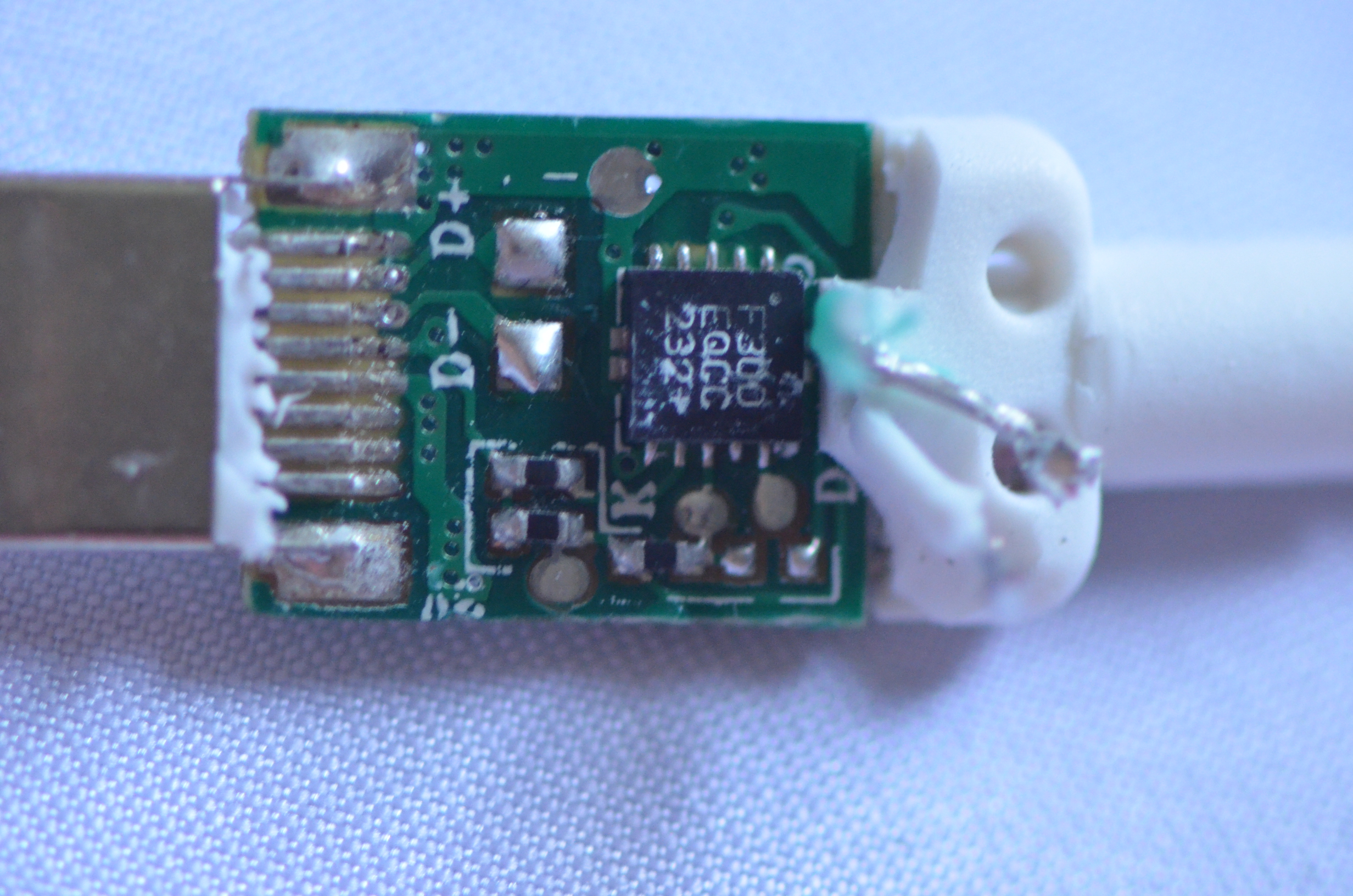
UPDATE: The person has authentication chips in it. Keep in mind this is super small, and magnified with a 1:1 macro lens...
2 of the standard cables from Apple arrived today. First thing I noticed is that the Lightning plugs are SMALL. Pinky fingernail size. The contact points on the plug are so tiny, it is hard to probe them with a multimeter. Also, they are tough and look really good. This is not a cable that is going to break easily. It is a fraction of the width of a dock plug and isn't going to snap off or have weird problems with locking, and so on.
Removing the plastic shell around the plug reveals a two piece metal crimp surrounding the solder area of the plug, as well as some injected silicone rubber cushioning. This plug is built like a tank, it is armored. Modders are going to want to give up on the idea of building their own charge cables/CLAS cables from scratch for this, until a DIY version of this plug surfaces. I don't expect a DIY version of this plug will go for that much, despite how pretty they are, since at wholesale you can get a healthy discount on these cables. The amount of force required to remove the crimp is insane, it is really on there. I got it off without completely destroying the plug, and was greeted with a generous coating of epoxy. Scraping all that off reveals a tiny PCB with the 4 wires of the USB cable connected to it. The PCB extends into the end of the cable, where I'm guessing the traces split off and cross to allow the two-sideness of the connector.
For modders, we have a tiny ~32awg pair of green and white wires which are for data. I'll post the exact specs when I get home. There is a 26awg red power wire for V+. V- duties are done by the cable's shield, which has several easily accessible drain wires for soldering to the plug of your choice. It is trivial to chop the end on this, strip it with a 14awg stripper to get the shield and jacket off, then, strip & solder these wires to a USB plug or micro USB plug if you wanted to make your own custom version of the long and annoying stock Lightning cable.
I will post the exact pinouts soon. For now, let's look at it this way: if you face the plug straight at you, the contacts facing up (and it should be the same on either side) are 1 2 3 4 5 6 7 8. Pin 1 is V- or shield, and it is connected to the shell of the plug on each side, so the power ground also serves to ground the shells of the cable ends together. Pretty standard USB layout. Pins 6 and 7 are the data pins (forget the exact configuration, will fix this in my next edit). Here's where we get to the strangest thing about this. Perhaps I just had a broken cable, but when the cable was fully intact, and afterwards, I tried to figure out where V+ connects to. I had the V+ wire stripped and hooked up to the multimeter, and I probed the crap out of the Lightning plug. No resistance, no continuity, to any of the pins on the Lightning plug. I will keep at it but for now this is a really strange mystery. The V+ wire is soldered to the little board inside the Lightning plug. Where it goes from there inside the PCB that extends into the metal contact end of the Lightning plug is anyone's guess. There does not appear to be any resistors or circuitry in this cable. It is just a regular USB cord as far as I can tell, so far. Except for this V+ problem. I have a 2nd lightning cord I can test here in a little while.


