Alien DAC v1.1 Construction Thread
Oct 1, 2009 at 3:10 AM Post #1,546 of 1,562
Ugh, I've killed my second DAC, to the same problem as my first. I've worked from GlassJar kits using USB power. I've packaged then both up in the same small Hammonds case using a slot high enough not to short anything, and I've even lined the inside with electrical tape for good measure.

With both boards, the DAC has worked wonderfully for months, then one side just stops outputting sound. I know there's not much to this thing beyond the main chip, so logic dictates that I'm doing something to kill the PCM2702s.

I'm proficient with a soldering iron and cant find any shorts or cold joints. Voltage on the 3.3 pad is spot on, and I see 4.7v at the 5v spot.

Any ideas what it could be? Bad hub power? Anything else?
 
Oct 1, 2009 at 12:15 PM Post #1,548 of 1,562
The symptoms you describe sound like the PCM chip is fried, unfortunately. One channel or another will go out, depending on which RCA jack/or similar "shocked" it. What amp have you been using with it?
 
Oct 2, 2009 at 1:54 AM Post #1,549 of 1,562
I've moved the DACs around between my SOHA and Millet Max, but mostly used them with my early-90s Yamaha Stereo Receiver (rx-v480, nothing special)

I understand that there's very little to the Alien besides the PCM, but it was hard enough soldering it on an empty board. I cant imagine trying to replace one on an already-populated unit, and certainly don't want to try before i figure out what keeps killing them.
 
Oct 2, 2009 at 3:53 AM Post #1,550 of 1,562
Quote:

Originally Posted by eddiewalker /img/forum/go_quote.gif
I've moved the DACs around between my SOHA and Millet Max, but mostly used them with my early-90s Yamaha Stereo Receiver (rx-v480, nothing special)

I understand that there's very little to the Alien besides the PCM, but it was hard enough soldering it on an empty board. I cant imagine trying to replace one on an already-populated unit, and certainly don't want to try before i figure out what keeps killing them.


Hmm ... well, there have been no reports of issues with the amps you mention. However, there have been cases (somewhere in this thread
wink.gif
) where one channel or another has quit working over time. I'm not sure there's been a consistent explanation but seems like some have had success at re-flowing the solder on the PCM chip.
 
Oct 23, 2009 at 2:46 AM Post #1,551 of 1,562
Quote:

However, there have been cases (somewhere in this thread ) where one channel or another has quit working over time.


Yes thats (unfortunately) my Alien Dac.
My problem is similiar but in my case the left channel only goes mute for a limited time. Unplugging the RCA jacks for a short period often helps. With a different (but still old) amplifier the dac ran fine for a couple of months, but just recently it stopped for like 20 seconds.
Perhaps it has something to do with the impedance of the amplifier, because when i used it with a compact amp with digital stepped attentuator the symptoms where much more frequent. But thats only wild guessing.
Btw my PCM was pre-soldered so i doubt its the cause.
Perhaps it could also be a faulty coupling cap? Dont know if thats possible though.
Good luck in finding the error.
 
Apr 15, 2010 at 6:44 PM Post #1,552 of 1,562
Hey guys,

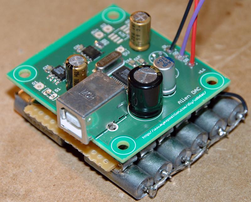
I read all 104 pages and then built my first Alien over the last two nights. It went really well. Everything worked great on first shot. Voltages test correctly, dac detected by mac os, sound is solid out both channels. I'm sure I lucked out a bit, but I also was very careful to test the destination of each pin with a DMM and spotted and fixed all bridges with a 30x microscope (cheapo one I bought from radio shack years ago).

I finished up pretty late last night, so I didn't get in much sound testing. I'm going to hold off until I case it up and put it to use before I touch on audio quality. I do have an expensive tube-buffered DAC of scott nixon design to compare it to.

If you are currently looking for parts, I have put together a pretty comprehensive BOM. Keep in mind that my BOM has a lot of extra parts to allow me to try different things (and build at least 3 aliens plus other stuff). Its more my inventory, so use it as a guide rather than a BOM. Definitely compare my parts to Alien DAC - Parts List to decide what you need. In all honesty, you aren't going to save money, time or aggravation over ordering the complete kit from glass jar. Its a great kit. I've marked which pieces come in the glass jar kit on my BOM in orange. I did purchase a kit and used some of the parts in this assembly.

My BOM:

djw AlienDAC BOM

I ended up using the Panasonic caps in C23, C33. On my next one I may use the Elnas since they are so cheap at digi right now and I have so many. I couldn't find the ESR on the Elnas, so I used the Lelons from my BOM on C13. They had the lowest ESR I could find.

I've used desolder braids in the past with very mixed results (mostly radio shack crap), but digikey part: EB1085-ND is absolutely amazing. It sucked up the solder like a wick and required no additional flux. It will be your best friend on the pcm chip or when fixing cold joints. I used a weller ST6 tip (digikey: ST6-ND) on my iron (wlc100 set to between 3 and 4, but closer to 4). A larger tip doing flood and suck would have been fine with the help of the braid I mentioned.

My approach was to get a tiny bit of solder on the tip and "swab" it on to each leg of the chip. I then followed up with the braid. Do not leave the solder on the tip for too long before swabbing it on. Keep your tip tinned and clean frequently. Make sure to test continuity to the destination of each leg after you've finished them all (touch very gently to the legs of the chip to avoid pushing it down onto the contact and getting a false positive). I found one leg that wasn't well connected and had to reflow solder to it. I took a similar approach on the first side of each SM capacitor and resistor. This allowed me to position with tweezers in one hand and dab on some solder with the other to lock it in place. I'd then follow up with a more standard solder approach on the second half and follow up with touching up the first (meaning: heat lead and pad with iron and add solder).

thanks to jeff of glassjar, tomb of here and diyforums and everyone here that had issues and posted them so I could learn from them : )

-daniel

4522775420_0f77f269d0_o.jpg
 
Aug 6, 2010 at 3:00 PM Post #1,553 of 1,562
Sorry to drag up an old thread, but I need some help. Over the last couple days I put together three identical AlienDACs. Only one of them doesn't detect correctly in Windows. The main problem is that L12 gets extremely hot, hot enough to melt the solder on the ferrite. I searched through the thread but only found a couple instances regarding shorts.
 
I've taken off L12, double-checked that it itself wasn't causing the short, and triple-checked the pins on IC1. I touched it up just now with some flux, making sure that there weren't any bridges using a stereo microscope at what I'd guess to be 15-20x magnification. I paid especial attention to pin 8, which I think is Vbus. I'm afraid to leave it plugged in for more than 5 or so seconds because I don't want anything else to melt or explode. Anyone have any ideas?
 
Aug 6, 2010 at 4:30 PM Post #1,555 of 1,562


Quote:
Well, check for a short with you DMM from V+ to V- and both to ground.  Perhaps you have something shorting beside one of the regulators.


Where should I check V+ and V-? I checked 5V and 3V3 to ground (the case of the USB jack), 5V gives 3.05KOhm and 3V3 gives 2.64KOhm.
 
I think L12 is the only component that gets hot. I'm going to try reflowing the solder of the hole that connects the bottom path to IC1 in case there's a short under IC1 that I can't see. All of my other solder joints look okay, though. I can upload pictures when I get home.
 
EDIT: okay, I just remeasured the bottom two pins on the USB receptacle (looking from the bottom side of the board) and can confirm there's a short between Vbus and GND. I never got a chance to reflow pin 8 of the PCM2702 but I have a feeling that's where my short is. If it's under the USB receptacle L12 wouldn't get hot, right? The Vbus path doesn't look very long...
do ferrites die if they're exposed to too much heat?
 
Aug 9, 2010 at 10:07 AM Post #1,556 of 1,562
I reflowed the connection to pin 8 of the PCM2702 on the bottom of the board and reflowed solder between pins 7, 8 and 9 just to make sure the IC wasn't causing the problem. I'm 95% sure there's no bridge under there. I reflowed C1 to make sure that wasn't the problem. Next, checking resistances with L12 removed... ground to negative C2 is ~0.5ohm, to positive C2 is 4.4ohm. Resistance across C1 is very high, increasing in the megaohm range (16-18Mohm). There's no connection between Vbus and ground on the USB receptacle with L12 removed. I'm stumped... does this still indicate a bridge under the PCM2702? Could it be a possibly blown IC? I had some difficulties soldering the pcm2702 on these boards, there's a chance I may have applied too much heat to this one.
 
EDIT: well, I got it working... not really sure what fixed it, but I desoldered C2 and added a new cap, made another reflow attempt, and slid fine tweezers between pins 8 and 9 to scrape away anything I couldn't see under the IC. One of these things did the trick.
 
May 27, 2011 at 1:52 PM Post #1,557 of 1,562
Whats the short story on performance when powered by the USB bus unregulated Vs. regulated down to 4.8v ?
 
I'm building one of these to install into my son's BH quickie and I've got all the parts on the way.  Our plan is to power it from the USB bus.  We won't be adding a seperate psu or powering it from virtual ground.
 
May 27, 2011 at 9:52 PM Post #1,558 of 1,562


Quote:
Whats the short story on performance when powered by the USB bus unregulated Vs. regulated down to 4.8v ?
 
I'm building one of these to install into my son's BH quickie and I've got all the parts on the way.  Our plan is to power it from the USB bus.  We won't be adding a seperate psu or powering it from virtual ground.


Performance with USB regulated is noticeably superior than with unregulated.  That's documented in this thread somewhere, but obviously, it will take some deep searches.  Many people around here can easily attest to the lack of quality in virgin USB power.  I don't mean to get up on a soapbox, but sometimes the primary difference in audio quality with many audio designs is the quality of the power supply.  Its effects should not be under-estimated.
 
The real question in power options with the AlienDAC is whether to choose the external power option with a separate, regulated supply.  I think the law of diminishing returns is hit in that case.


Sep 5, 2011 at 12:29 PM Post #1,559 of 1,562
Have finished my 1st alien using an adjustable regulator for IC3. I am planning to use it powered from USB. I have tested the voltrage and get 3.3v from the 3.3 pad, but only 3.96v from the 5v pad. I used 31.6k for R31 & 11.5k for R32 and all the joints look good and no bridges i can see.
any ideas?
 
Sep 22, 2011 at 12:24 AM Post #1,560 of 1,562
Anyone have any success connecting the alien dac to an ipad via the usb dock connector?  Im not sure if this is the right thread for this but I have searched the site and this thread and haven't found anything.  I just built and alien dac with regulated usb power from glass jar audio.  I know if i plug in a powered usb hub that would probably work but im looking for a battery powered portable solution. Any help would be greatly appreciated.
 

Users who are viewing this thread

Back
Top