A Very Compact Hybrid Amp
Mar 2, 2011 at 11:23 AM Post #2,176 of 2,218
Quote:
I know I know, I just wanna see this new white on black snazzzz.

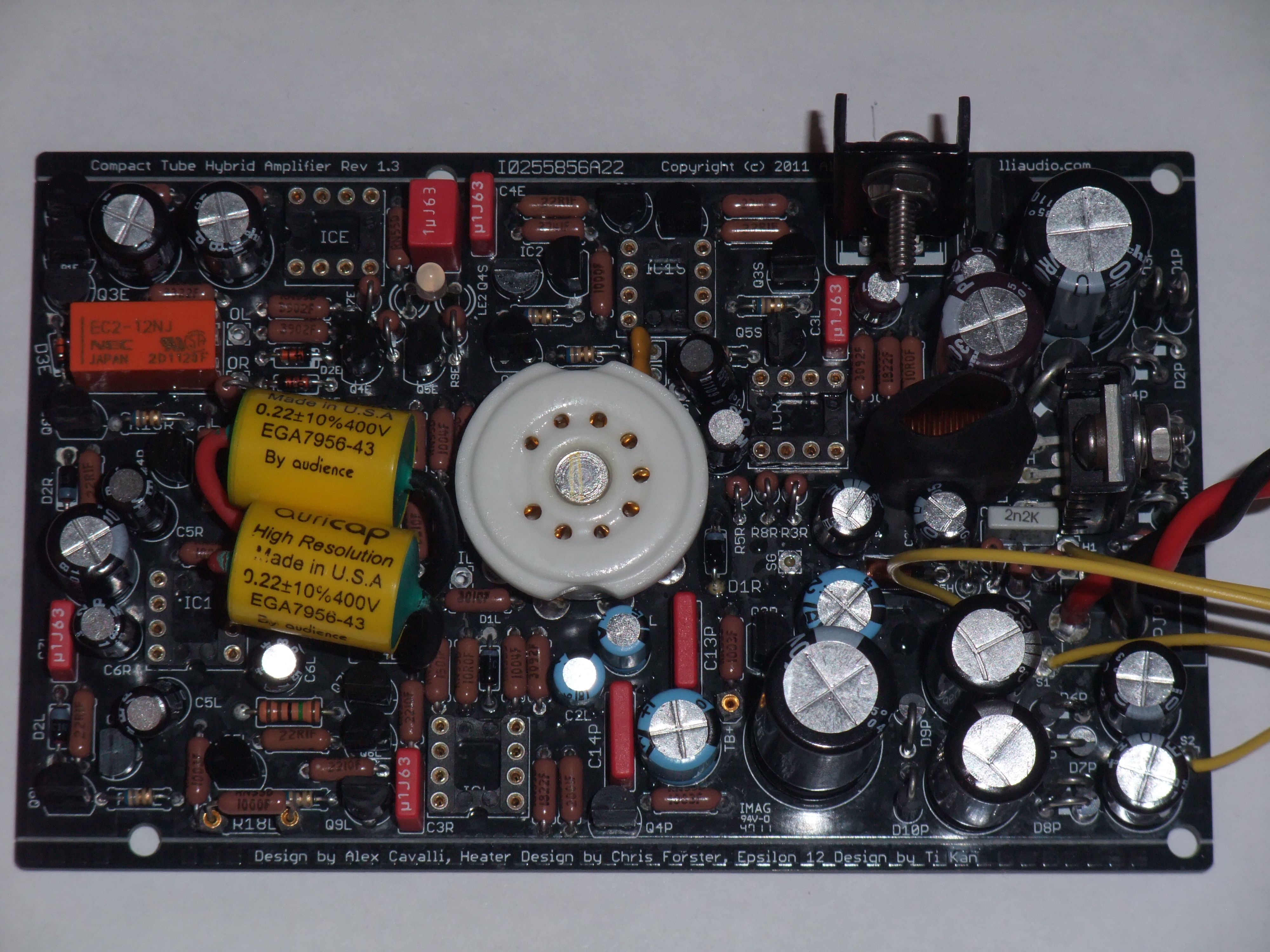
We thought it might be better to create a new DIY thread for new rev CTH PCB builders:
 
"the CTH (Compact Tube Hybrid) Rev A thread..." - http://www.head-fi.org/forum/thread/542279/the-cth-compact-tube-hybrid-rev-a-thread
 
A lot of the (old) issues raised in this huge thread have been addressed through parts spec changes in newer/newest BoMs & PCB layout improvements in the latest PCB rev.
 
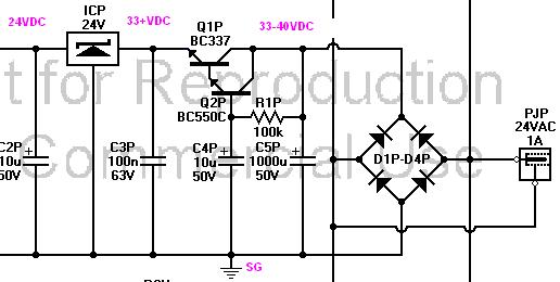
This is not to say CTHs using this new PCB rev will sound different/better than CTHs using earlier PCBs that have corrected parts installed (in particular 330uf C3H & BC337 Q1P). 
The changes in this new rev are largely ones that make building easier (see the new Rev A thread for details).
 
Apr 27, 2011 at 12:38 PM Post #2,177 of 2,218
Finally finished mine (yes, it's the original and not the Rev.A). I've had a few troubles, notably on finding a wall-wart. My first one was 24 VDC, despite being indicated as VAC. I am now using the WAU24-1000, though I've had to snip the original connector to replace it with a 2.5mm one.
 
Now, the only trouble it has is that turning the volume pot too fast trips the e12. The pot is the alternative one on the BOM, the Panasonic EVJ. If anyone has any idea how to fix this, it would be appreciated.
 
Apr 28, 2011 at 9:14 PM Post #2,178 of 2,218
Nevermind, I found the cause: I had linked the input jack's ground to the output jack's ground. Linking the input jack's ground to the volume pot grounds instead resolved it, and the e12 no longer trips when changing volume.
 
I was also blowing up some fuses when inserting the power connector. I made the panels out of aluminium, and the connector was shorting to the case. I widened the hole and put a vinyl gromit to isolate the conector.
 
Apr 29, 2011 at 9:52 AM Post #2,179 of 2,218
New update: smoke! The moment I connected it to my E-mu 0404 USB, smoke came out of something close to the ICP. There was not even any signal going in! I'll have to get replacement parts for the 2-3 transistors and capacitors there.
 
Apr 29, 2011 at 4:48 PM Post #2,180 of 2,218
That's a shame about the smoke.  I was a bit surprised that your CTH survived the IG/SG/OG 12V dead short (OG sits 12V above IG/SG).  Perhaps that damaged something.  Maybe it was the A/C connector to case that did it.  Or maybe something is still mis-wired that caused the smoke (e.g. another ground problem aggravated by connecting 0404's ground?).
 
Perhaps your CTH was fine on the bench, e.g. it passed your setup measurements:
http://www.cavalliaudio.com/diy/cth/main.php?page=setup
but things that shouldn't be interconnected were (e.g. metal case + not using insulated jacks such that the wiring requirements did not hold:
http://www.cavalliaudio.com/diy/cth/images/CTHWiringDiagram.jpg)  Nothing should interconnect (read 0 ohms) except IG/SG/Case.
 
You'll have to really check these things if replacing select parts does get your CTH going again.  Good luck!
 
Apr 29, 2011 at 6:00 PM Post #2,181 of 2,218
Well, the crazy thing is that it still works. It's just a theory, but I think it was because I plugged the E-mu's input to the CTH's output (I was going to test it as I had done on my other amps). The very high input impedance may be drawing too much, or something like that (I don't have much of an electrical background).
 
In any case, the CTH and the Emu don't like each other, and will no longer be connected to each other.
 
Jul 18, 2011 at 10:36 PM Post #2,182 of 2,218
Does anyone have a listing of the changes in the E12 circuit between the original BOM(prototype time) and the most recent one (for the original circuit design, not the new Rev).  I sold my CTH and the buyer is having E12 tripping problems. I never had an issue with this but I didn't use it the same way he is.  I suspect its partly due to using Thunderpants at a high volume, with the bass eq cranked as well, and his particular choice of music (electronica).  Has the E12 circuitry been reduced in sensitivity and if so, any suggestions on what would need to be done? 
 
Jul 18, 2011 at 11:13 PM Post #2,183 of 2,218
Mr Slim - I'd have to search here myself to find it as I don't recall exactly which parts were changed & to what values.... IIRC runeight has made a post in the last 6 months or so about it so maybe search for his posts?
Also IIRC the original BoM is up on cavalliaudio as well as the newest/latest one.
 
Oct 20, 2011 at 10:51 PM Post #2,184 of 2,218
I need some help guys.  I finally got my CTH all populated and wired up but  I am having a problem.  No smoke and the LED light turns on but SG-OG is 1.3 VDC and SG-OL and SG-OR is 0.  I have no idea what to do.  I built this using a kit from Waitrob I got almost 2 years ago which I should have finished back then.  If anyone could help I would greatly appreciate it.
 
Thanks
 
 
Here are some pictures of the amp,
http://i11.photobucket.com/albums/a175/bnorton/Top-1.jpg
http://i11.photobucket.com/albums/a175/bnorton/Bottom-1.jpg
 
Oct 21, 2011 at 7:43 AM Post #2,185 of 2,218
blaken - I assume you mean your output relay does not latch.  Key measurements for that are OL-OG & OR-OG going into the relay.  IOW, w/o relay latch, checks on those pads will read 0.  You could tack temporary wires to OR/OL going into the relay for this test.  Looking at the PCB relay mount, these are the middle pads of the 2 triplets:
http://www.cavalliaudio.com/diy/cth/main.php?page=boards
 
But, before the above, the 1st steps in any debugging are:
1)  double-check soldering job esp. looking for bridges.  Assuming the underside has been cleaned (e.g. w/90%+ alcohol),
2)  double-check the correct parts are in the correct places and correct orientation on the board,
3)  Conduct the setup test here & let us know the voltage readings from it:
http://www.cavalliaudio.com/diy/cth/main.php?page=setup
Most measurements are with-regards-to SG.   Also please let us know the heater readings (voltage bet pins #4 & #5) for both 6V & 12V heater switch positions.
Be very careful with your probes when taking these measurements (e.g. I've taped pins to mine for CTH tests).
4)  Try to post clear/good resolution pictures of your build top & bottom
 
 
Oct 21, 2011 at 10:07 AM Post #2,186 of 2,218
>  SG-OG is 1.3 VDC
 
Though my last post should still be followed, I see this is a fail for the 1st setup test (expect close to 12V).  Let us know your ICP voltage measurements: middle pin to input pin (I/right on PCB image) and middle pin to output pin (O/left on PCB).  We should be getting close to 24VDC out of it.  If we are then there may be problem w/TLE2426/rail-splitter.
 
Oct 21, 2011 at 1:45 PM Post #2,187 of 2,218
 
Thanks for helping CF.  I am at work right now but I will take those measurements as soon as I get home. (I should have refreshed by browser before replying I wrote all of this without seeing your second post.  I will get all the data tonight.)
 
1) I did look for bridges but I will again.  I did clean the board with 91% alcohol and a tooth brush twice.
2) All the orientations look good but I haven't got out the magnifying glass yet to check parts but I will.
 
 
I want to make sure I am explaining myself as to what I was doing.  I can follow instructions and a schematic but as to what is going on where in the circuit I am clueless.  I was trying to follow this step in the setup
 
"Measure between OG and SG. This should be very close to 12V. If it's not there might be a problem with the TLE2426 or with one of the devices in the rail splitter."  
 
I had the negative lead of my volt meter on the SG pad and the positive lead on the OG pad and I was expecting this to be 12v but it was 1.3 VDC and SG to OL/OR was 0 VDC.
 
You want me to measure the voltage before the relay. Below is the silkscreen with Red and blue dots to where I think you want me to take the reading from to SG.
 
http://i11.photobucket.com/albums/a175/bnorton/CTHSilkScreen.jpg
 
Also please let us know the heater readings (voltage bet pins #4 & #5) for both 6V & 12V heater switch positions.
 
Is this with or without a tube in.  I am assuming without.
 
Sorry for the rudimentary questions I just want to make sure I don't damage anything further and thanks for the tip about attaching pins to my probes.


Oct 21, 2011 at 2:44 PM Post #2,188 of 2,218
>  I wrote all of this without seeing your second post.
 
Yeah, my fault for not speaking to your 1st step / 12V vs 1.3V test fail.  The primary measurement/test right now is your 24V regulator/ICP readings. That can be done w/ or w/o tube. 
If you get 24VDC out of it (its center pin -> Output pin) again this may be a problem in the rail-splitter circuit (which is primarily responsible for making SG-OG read 12VDC).
 
To speed things you could then carefully go ahead & do the high-voltage TB+ / SG and low-voltage heater (measure across tube socket pins #4 & #5) tube-in readings.
 
And yep, those dots in your image are correct if we end up needing to do the true/pre-relay DC offset reading.  We'd do that only if/when we pass all the standard "setup" tests & still had a problem.
 
Edit: Don't see a heatsink on ICP/24V reg in your pic, it must have one.  And please again check the proper opamps are in the proper sockets (there are singles & doubles) plus the transistor locations (it is color-coded though):
http://www.cavalliaudio.com/diy/cth/images/CTHPartTransistorLocations.jpg
 
Oct 22, 2011 at 1:14 AM Post #2,189 of 2,218
Ok ICP center to IR = 0v  ICP center to OL didnt measure.  What I mean by that is when I measured IR my multi-meter read 0v but when I measure OL it kept bouncing around in the mv which is what it does when there is no continuity.
 
TB-SG was 110v
 
"low-voltage heater (measure across tube socket pins #4 & #5)"
"Also please let us know the heater readings (voltage bet pins #4 & #5) for both 6V & 12V heater switch positions."
 
Sorry I want to make sure I am clear on this before I do it.  Do you want me to measure (#4 to #5) or (SG-#4 and SG-#5).
 
" Don't see a heatsink on ICP/24V reg in your pic"   
 
 I took it off for the picture so everything around ICP would be easier to see.  I put it back on before I did any more testing.
 
"And please again check the proper opamps are in the proper sockets (there are singles & doubles) plus the transistor locations (it is color-coded though):"
 
I went over every transistor and opamp and verified it is the right one in the right orientation.  My only question is Q1P.  The bom says it is a BC337 but the color chart here http://www.cavalliaudio.com/diy/cth/images/CTHPartTransistorLocations.jpg has it as a BC550.  I put in a BC337.
 
Thanks again for your help.
 

Users who are viewing this thread

Back
Top