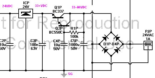
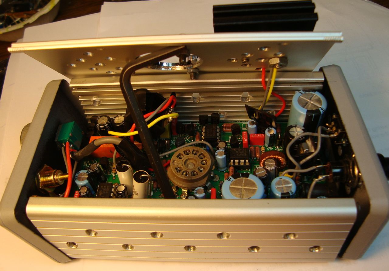
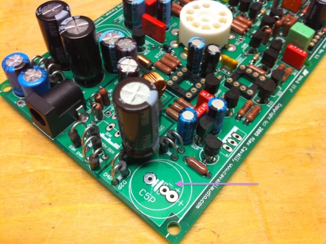
That diagram is perfect. I will get those measurements taken. Do you know what q1p is suppose to be? The discrepancy between the bom and the color diagram has me concerned. I will start checking the other parts in the green box.
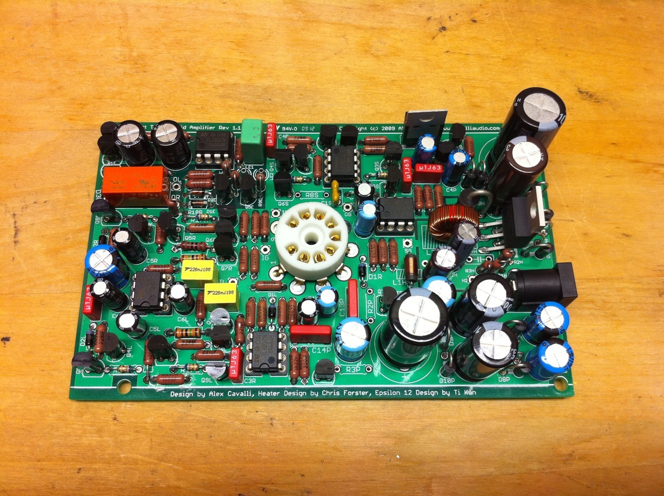
Ack, forgot your Q1P query. Yes, BC337 is the proper Q1P sub for BC550 in your version of the CTH PCB.
And if you've no 24V out of ICP then don't bother with the "75plus" measurements in the diagram (yet), and very close review/testing of parts & solder joints in the green boxes makes sense. If nothing seems bad there then try to measure the "33+, 33-40VDC" points below WRT SG when powered.
That diagram is perfect. I will get those measurements taken. Do you know what q1p is suppose to be? The discrepancy between the bom and the color diagram has me concerned. I will start checking the other parts in the green box.
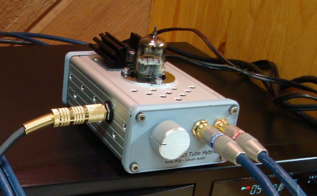
IT LIVES! Thanks so much for your help cfcubed. To no ones surprise it was builder error. C4P was backwards. After switching it and then double checking every other cap on the board and going through all the setup tests again it fired up just fine. My input leads are way too long and picking up a little noise but after situating those it sounds great. I've been putting it through it's paces for the last couple of hours and I couldn't be happier. I am going to grab an RK27 for it and one of amb's nifty ε27 boards.
One last question does SG really need grounded to the case since nothing else is?
> C4P was backwards. ..... I've been putting it through it's paces for the last couple of hours and I couldn't be happier.
Great news that you found/fixed the problem & are happy Note though that polarized caps don't take kindly to having reverse power, they can explode (another reason to wear eye protection). Lesser symptoms are case swelling or "poor" performance. I'd replace a cap that's been reversed or had its voltage rating exceeded.
> One last question does SG really need grounded to the case since nothing else is?
Yes, if its a metal case - grounds the case against noise (btw IG=SG). And ground pots w/metal shafts too (if not ground through metal endplates, search RK27 ground screw).
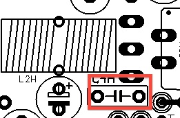
Sorry Cfcubed but I am having another problem. I went ahead and replaced C4P then cased up my CTH but now it just humming very loudly as in full volume loud. I ordered a spare c4p so I tried a different cap since that was the only thing that changed but it didn't do any good. I already threw away the original one but I doubt that's the problem. During casing I rewired the power switch, output jack and pot. For the pot I used an amb ε27. The hum occurs with no input and the pot unplugged. I have searched the board for any lead that could have got bent over but have found nothing. It has been cleaned with alcohol. The c4p from the original bom was unavailable so I got this one.
My bet is that your hum after case up has nothing to do w/C4P, though I'd carefully review that section visually & w/DMM as you worked there. The C4P replacement you linked to is fine.
Sorry Cfcubed but I am having another problem. I went ahead and replaced C4P then cased up my CTH but now it just humming very loudly as in full volume loud. <snip>
I also tried different tubes and checked all the voltages.
I just can't win with this amp lol. I figured out what the problem was. The ε27 board has 4 pins for in and 4 pins for out. The outer pins are L and R and the two center pins I assumed were ground. On the board I have the G is centered between the two middle pins. Well it turns out at least on my board only 1 of those pins is ground and the other is nothing. So on the (in) of the pot it was grounded but there was no IG going out to the board.
So it's working again... sort of. One channel is at full volume no matter where the pot is and the other is working as intended. I checked the resistance from my input jack all the way through to the IR/IL pads they are fine. I tried different tubes a 12v and a 6v with no change.
I should have just left well enough alone when I had it working and just leave out the blue velvet and everything would be fine but It seems like I might have really screwed something up this time. The only saving grace is I could just leave it running at full volume all the time and use my input device to control the volume. The only thing I can think of is I zapped something when I was trying to trouble shoot the other problem.
> One channel is at full volume no matter where the pot is and the other is working as intended. I checked the resistance from my input jack all the way through to the IR/IL pads they are fine.
This can only be external to the CTH PCB, it is a problem between your input jack & the IG/IR/IL pads. When you check the resistance are you also checking that your pot is sweeping the CTH inputs to ground?
IOW, input attenuation consists of sweeping the amp's inputs (IR&IL) from ground (IG/input gnd) when @ zero volume to the input jacks L&R when @ full volume.
Don't give up
> I should have just left well enough alone
I'd vote for that as DIY's mantra We all get bit by this one time or another, runeight even made that his sig
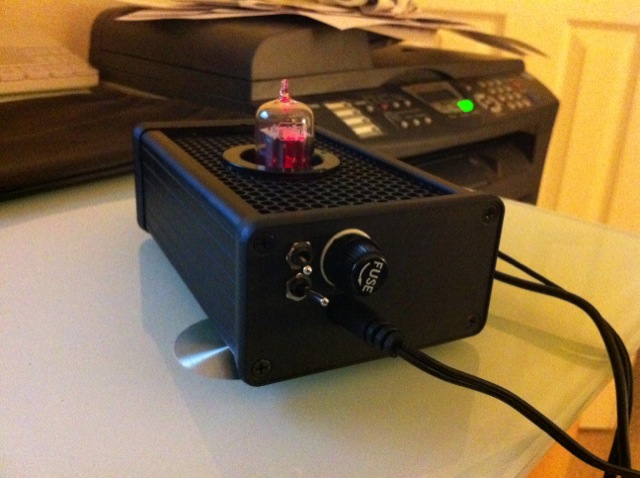
After reading your comment I had one of those head slapping DUH! moments. The ε27 board was made for balanced input so the L/R grounds don't connect. One of my channels was properly grounded and the other was not sweeping to ground. So after making a little jumper that problem is solved. I just need to get it cased back up and possible adjust the gain a bit but I used sockets on the gain resistors so that will be easy. I was thinking of not leaving well enough alone and replacing my input cabling with shielded cable. I have some canare star quad somewhere. I just can't stop myself.
After reading your comment I had one of those head slapping DUH! moments. The ε27 board was made for balanced input so the L/R grounds don't connect. One of my channels was properly grounded and the other was not sweeping to ground. So after making a little jumper that problem is solved.
The e27 is designed for single-ended input, not balanced. In fact, the e27 uses a common ground plane for all inputs and outputs. So, I am most curious what you actually jumpered to solve the problem.
You should at least consider attaching the ground leads of both input sources as well as running at least one of the output grounds to both channel input grounds of the amp.
When measuring my board the 3 marked points I thought were ground did not have continuity to the ground plane.
The board I have is a newer revision than this one. There are also two more ground points on the one I have which was nice for grounding the pot itself. I jumpered the two inner ground pins on each side and jumpered G+ to GI.
Hello, I'm finishing the build of my CTH i started one year and half ago, its all populated and wired but I'm getting some troubles.
When doing the first measures OK, but with a tube the e12 switch green and immediately return to red.
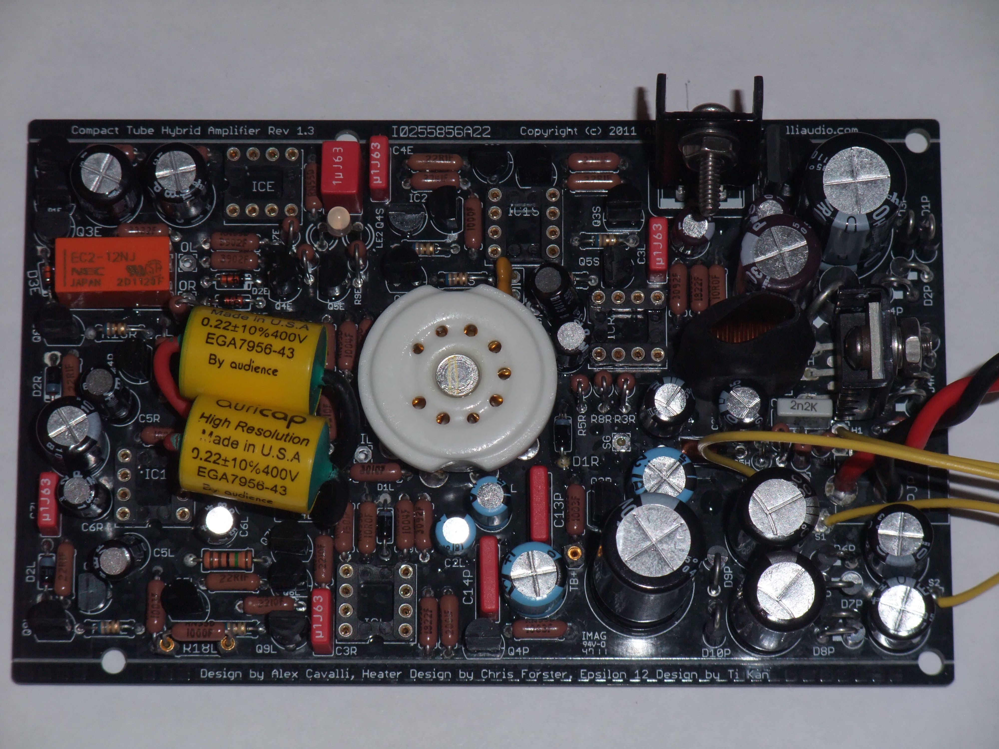
Hi guys. I have been having some issue with my CTH, its the original board, not rev a. When I power it up, R16R starts smoking, I did replace that, and also replaced Q8R (just because it was near and I had a spare), but problem persists. Any idea what can be causing this? Thanks in advance for any tips troubleshooting this.
Hey guys is there any Hybrid amp for CIEMs that give me warm lush mids/vocal and fun extended Treble which is fun? also fun bass if possible
i had WA7 with EH Tubes, was't this fun :< Super mids i know but the Treble and Bass were tube level though that the EH tubes were the best option for that
desktop amp if possible else i will go with the current options :/
PS: i am a Treble head and i don't mind a punchy bass that isn't in the way of my forward/sweet/lush/transparent mids
This site uses cookies to help personalise content, tailor your experience and to keep you logged in if you register.
By continuing to use this site, you are consenting to our use of cookies.


") Note though that polarized caps don't take kindly to having reverse power, they can explode (another reason to wear eye protection). Lesser symptoms are case swelling or "poor" performance. I'd replace a cap that's been reversed or had its voltage rating exceeded.
Note though that polarized caps don't take kindly to having reverse power, they can explode (another reason to wear eye protection). Lesser symptoms are case swelling or "poor" performance. I'd replace a cap that's been reversed or had its voltage rating exceeded.
