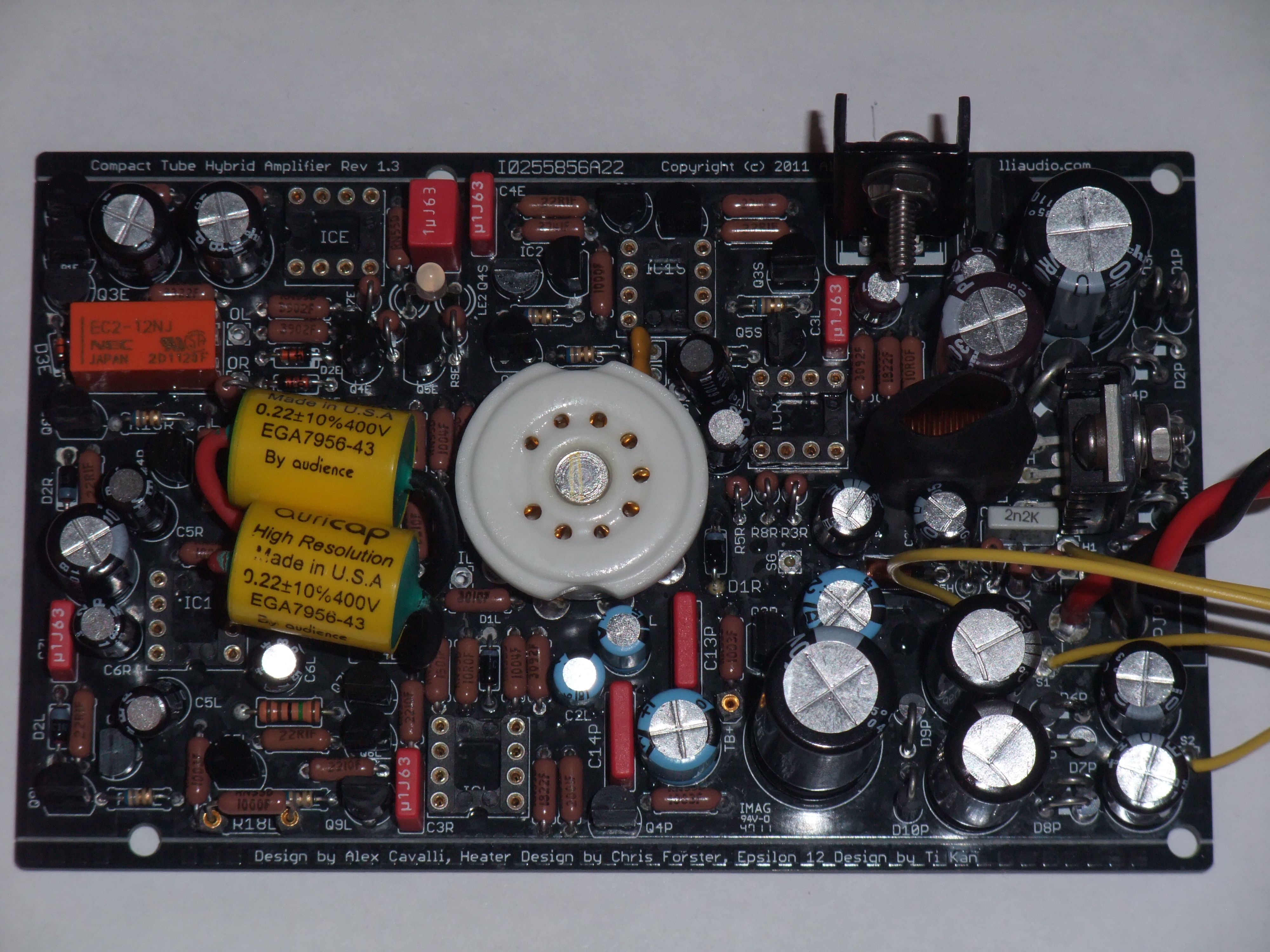
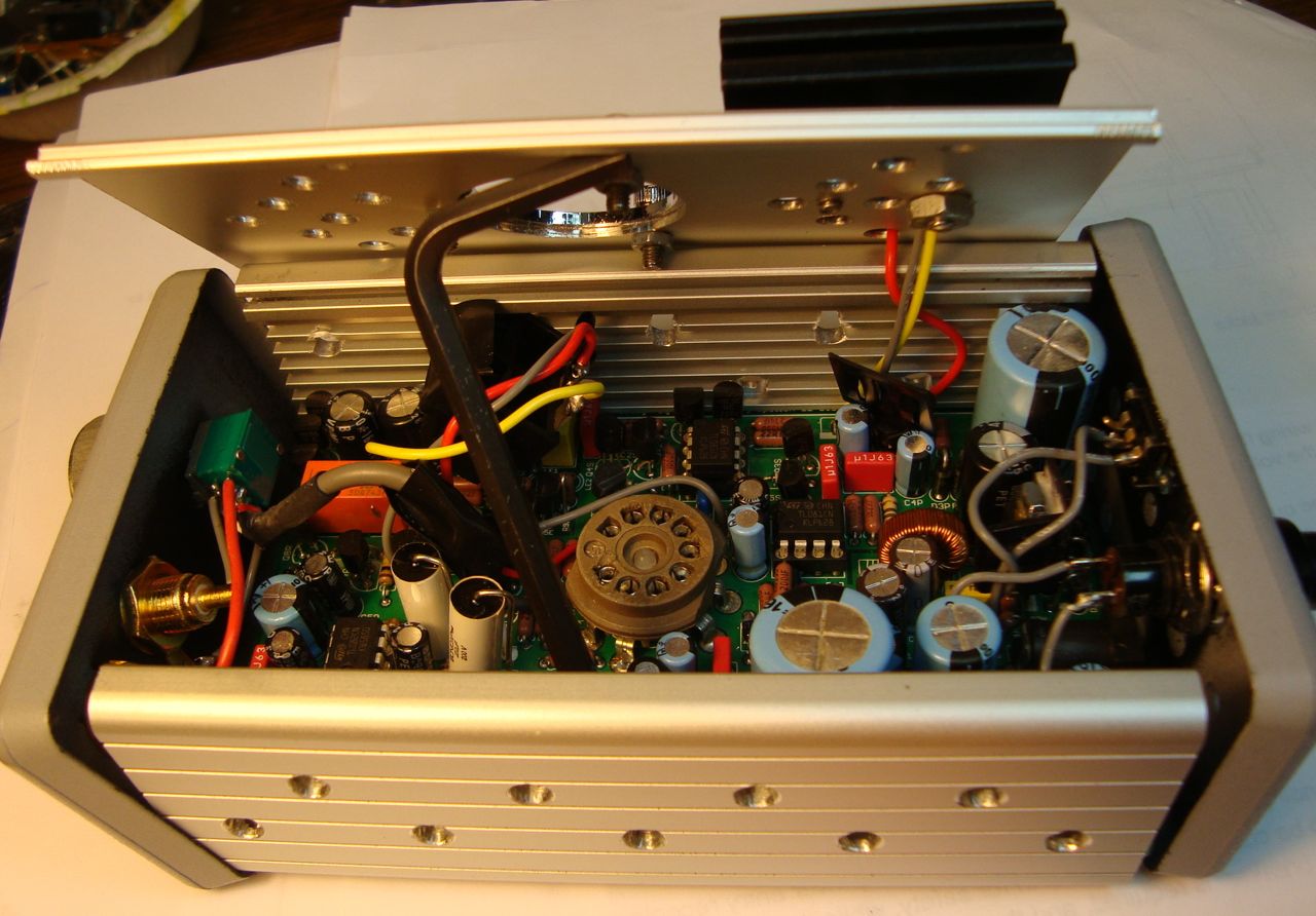
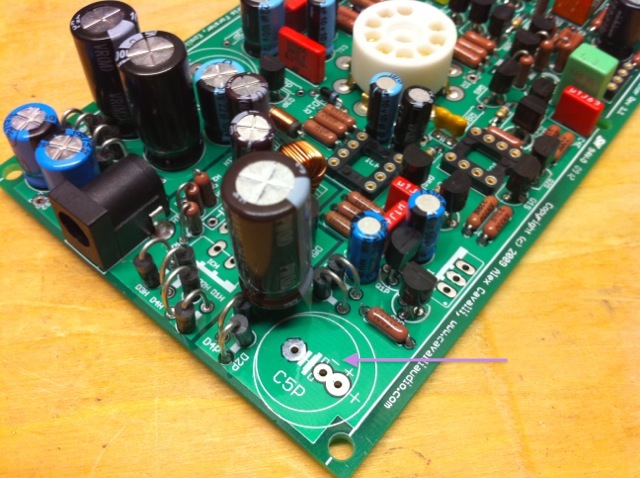
Did the amp work before case up? You should test an amp on the bench before casing it up - its easier to do & it let's you know when any problems originated (e.g. worked pre-casing)
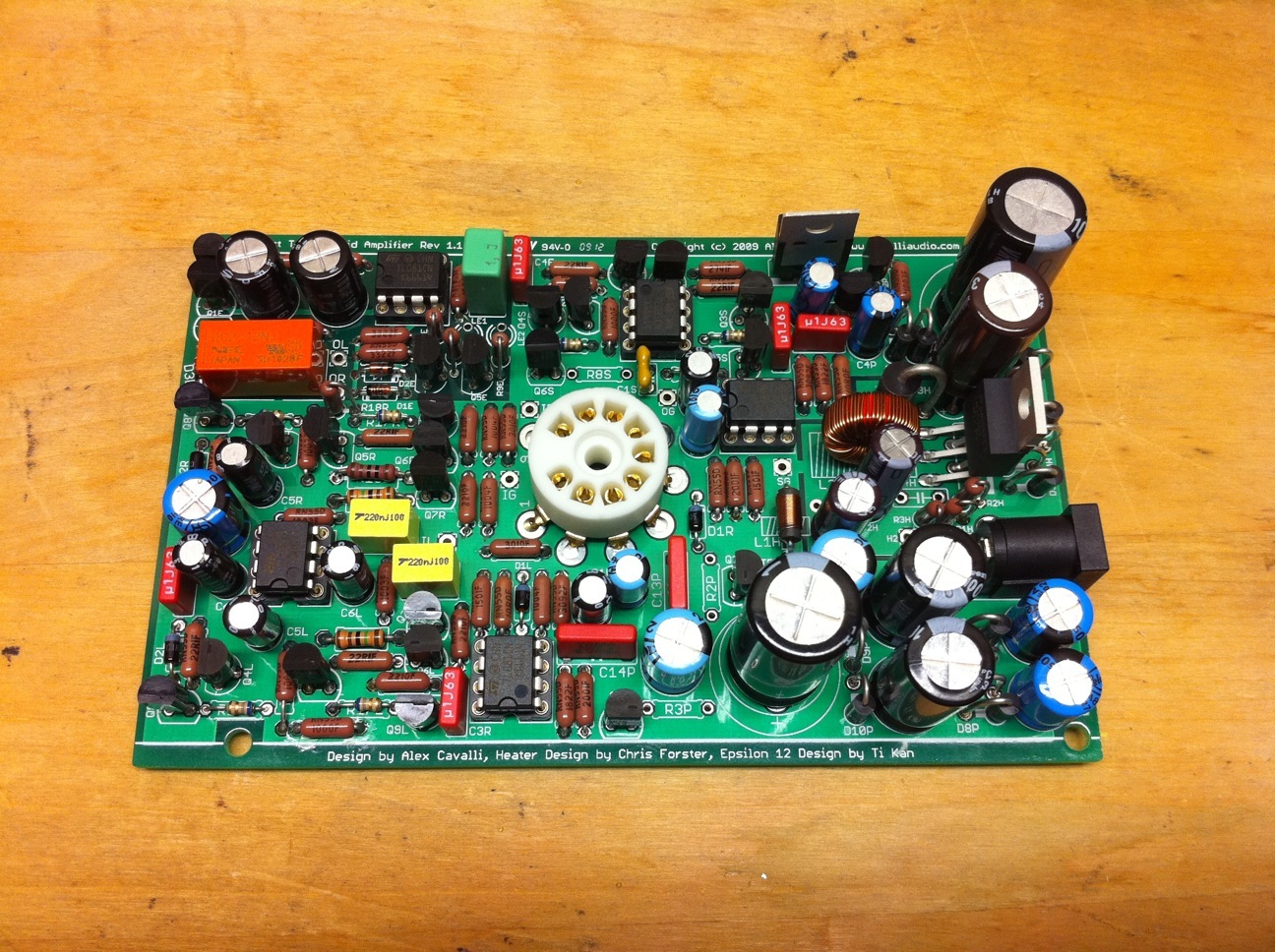
You will need to go through Setup & find all your Vs that deviate from it:
http://cavalliaudio.com/cth/main.php?page=setup
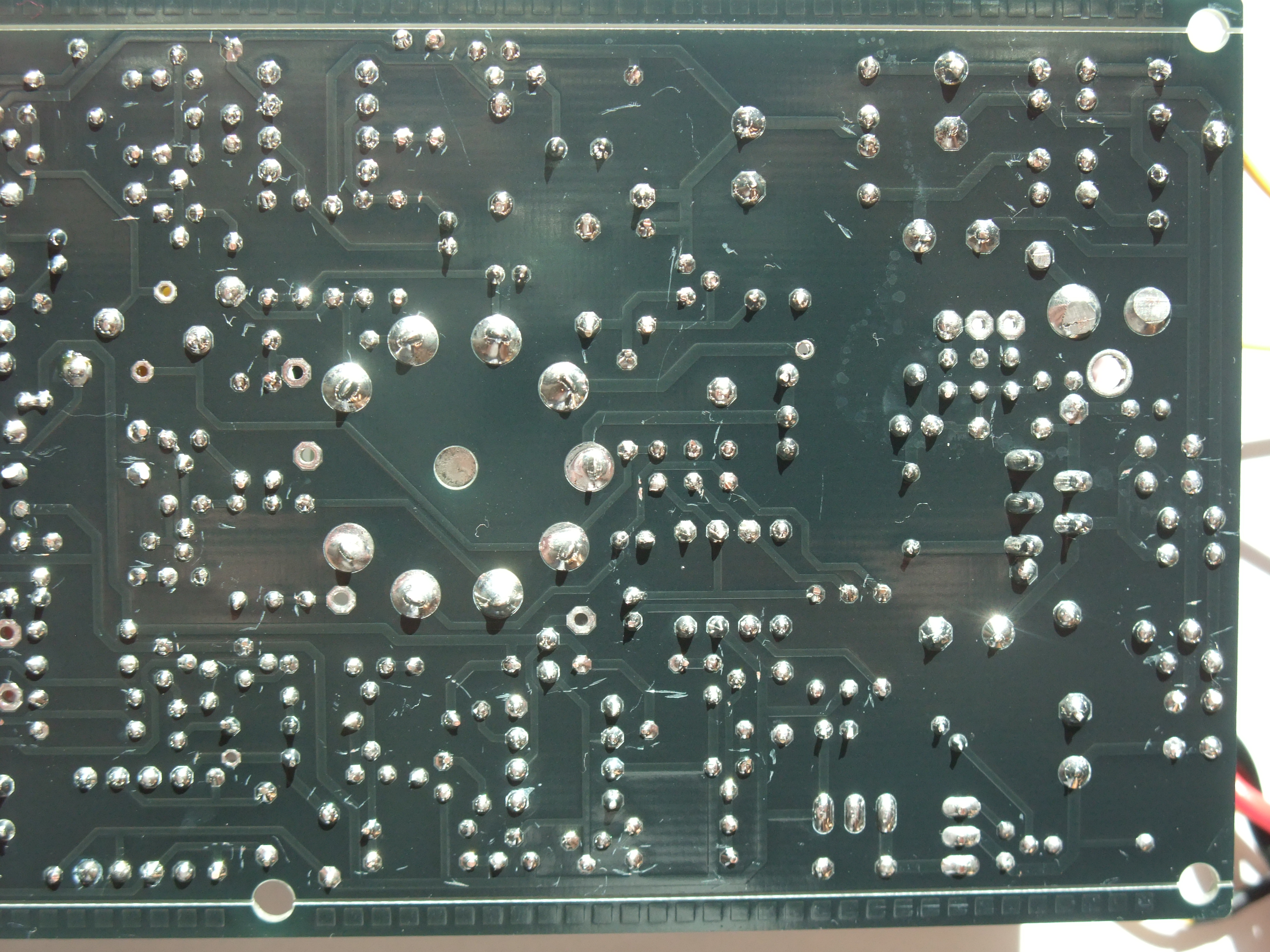
Be careful doing this, I tightly tape pins to my probes leaving only the very tips exposed. Do this w/PCB out of case of course.
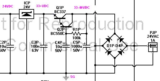
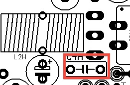
BTW one basic thing is
OG is NOT = SG (headphone must not be grounded to case...), so you may 1st want to make sure of this before pulling the board (OG-SG ohms) & checking all your setup measurements.