I'll bet your version sounds quite good.
I think the "look Ma...No caps" version sounds different but
like everything, I'm sure different people will favor one or the
other for their own reasons.
You can "tune" the amp for different impedance headphone by
changing the Voltage/Current values. For low impedance, use
more current and less voltage. For higher impedance use
lower current and more voltage.
If you are building the traditional style with a resistor as the
current source, Rsource = Headphone impedance.
A general value of Rsource = 100R drives most cans well
enough.
If you want to lower the output impedance you can add
an op amp (or jfet or tube) stage in front and put the MOSFET
in the feedback loop.
Quote:
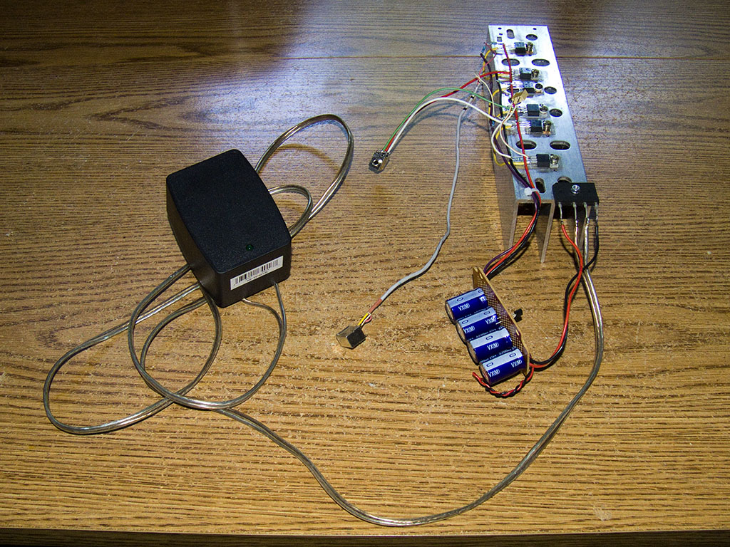
Can you tell any significant difference between the AC and DC coupled version of this amp?I'm using it with the caps for almost an year(with some modifications to increase PSRR).I've integrated it with a preamp module,and it's a complete amplifier.I'm using WIMA Polypropylene input and Panasonic FM low-ESR output caps.I like it,though it's quite revealing with powerful in-front mids,slightly colored upper mids.It depends almost to the opamps used only.
I wonder if it can drive high-impedance headphones ?Never tried.