Post pics of your builds....
Jan 8, 2009 at 7:50 AM Post #4,126 of 9,811
I've been meaning to post pics of the stuff I've been working on for a while, but laziness always gets the better of me. I'll do this chronologically starting with me Meta42, which I recently re-cased and added a battery-pack.
DSC00852.jpg

DSC00855.jpg

DSC00854.jpg

DSC00853.jpg


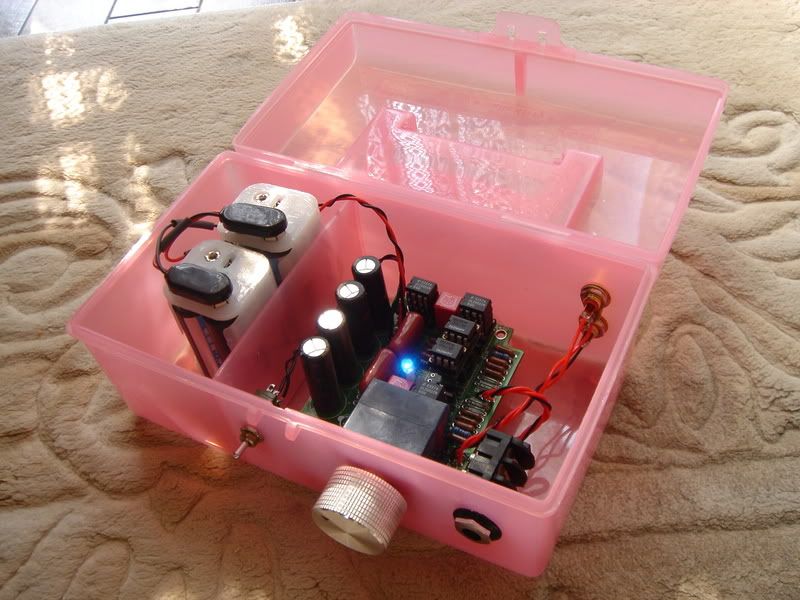
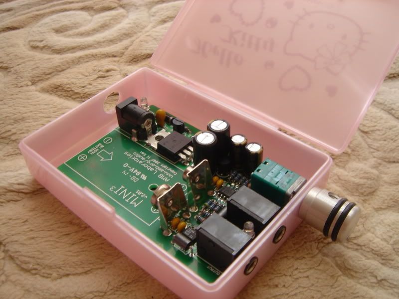
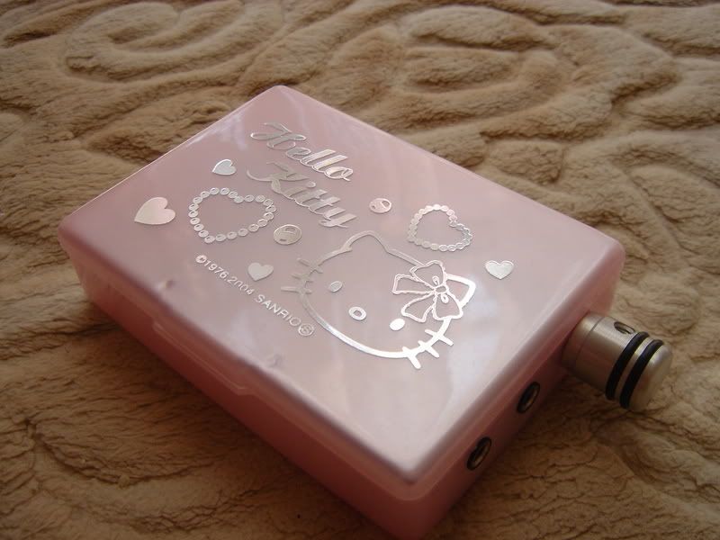
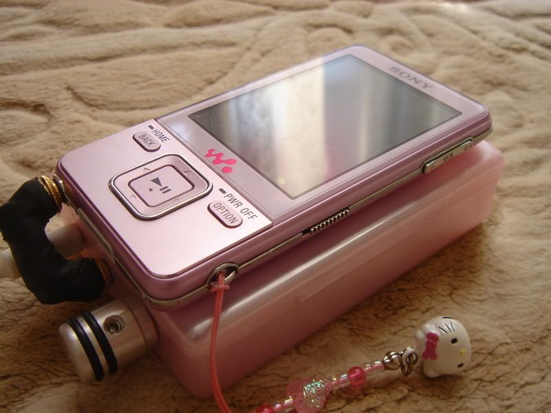
Then the Mini^3 I built recently.
DSC00886.jpg

DSC00887.jpg

DSC00892.jpg


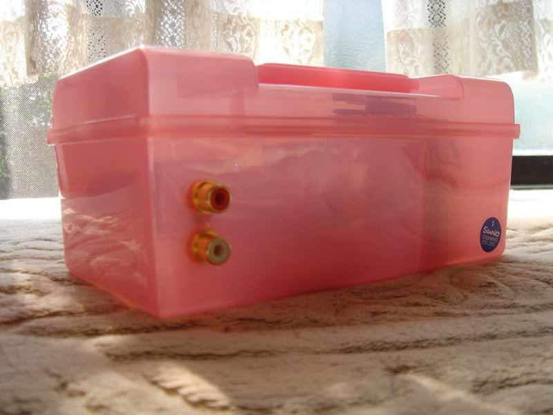
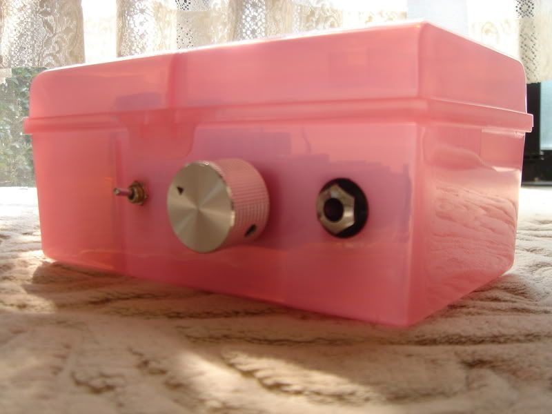
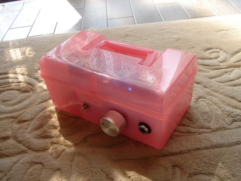
and finally the JaM Box. I didn't actually build any of the parts for this one, just gave them new homes.
DSC01028.jpg

DSC01045.jpg


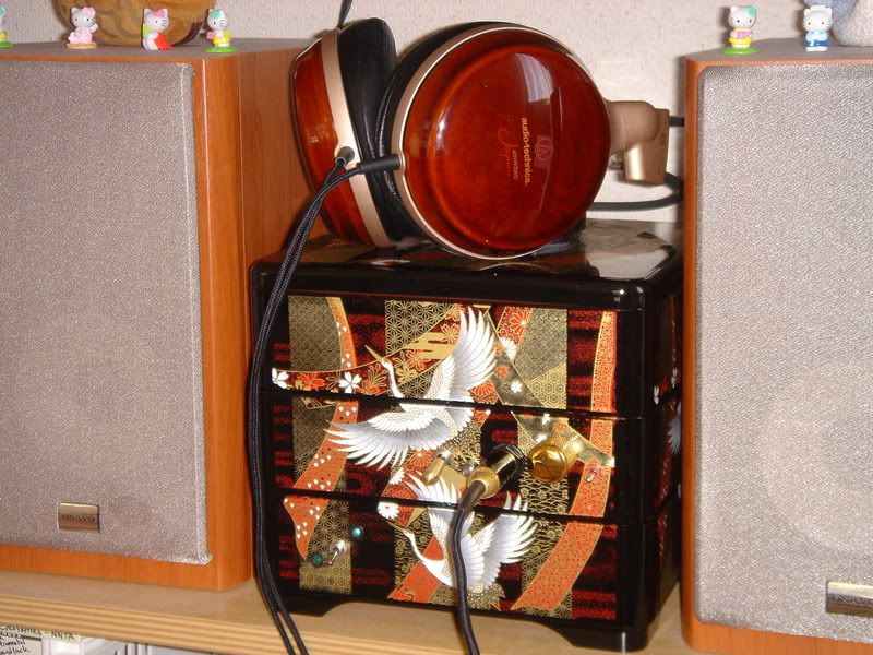
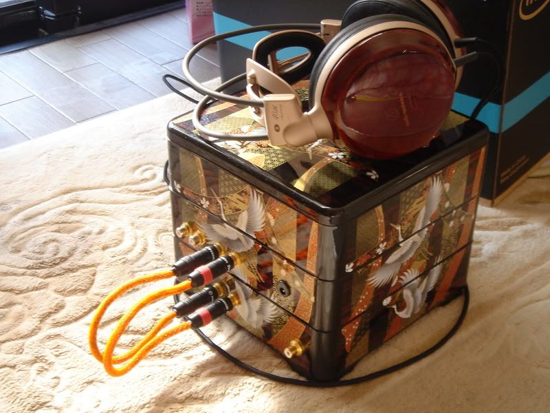
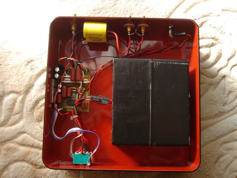
From the bottom, this is the Ack! dAck!
DSC01033.jpg


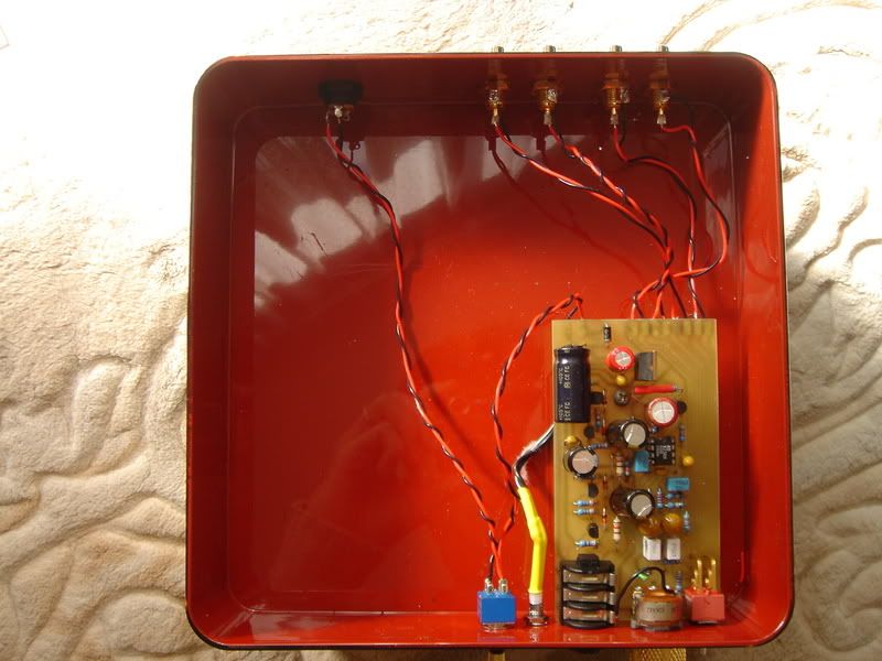
And this is a Graham Slee Solo in the middle.
DSC01034.jpg


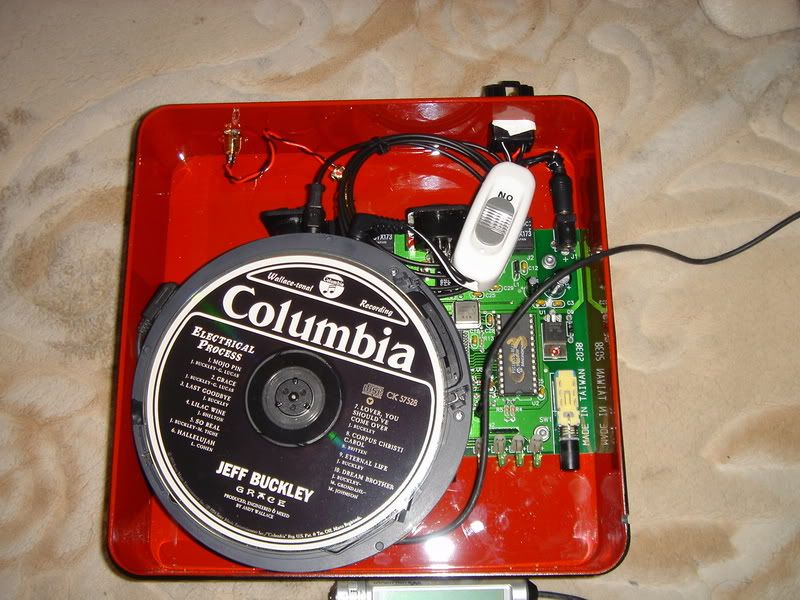
The top is an old Discman, along with an M-Audio Co3 to convert the optical output to coaxial for the dAck! to digest.
DSC01053.jpg

It's kind of a mishmash, but I think it's pretty cool and it sounds really nice with the PFR-V1.
 
Jan 8, 2009 at 8:23 AM Post #4,127 of 9,811
Punslayer, your DIY projects are beautiful, unique and charming.

I am especially impressed with the JaM box, even if you didn't actually construct any of the innards. Many DIYers here are stymied by case work, but clearly you have risen above that.

I see a lot of you in your projects. Great work.
 
Jan 8, 2009 at 8:56 AM Post #4,128 of 9,811
Sherwood,

thank you very much! My goal in DIY is not just to get good sound, but good sound that reflects my character so your words mean a lot to me. I'm quite an amateur at all this and I can understand why people are daunted by casework (I really need to get some proper tools) but I think that the reward is well worth the effort.
 
Jan 8, 2009 at 9:10 AM Post #4,129 of 9,811
Id be worried about those plastic cases having or forming static charges in them =X
 
Jan 8, 2009 at 9:14 AM Post #4,130 of 9,811
Quote:

Originally Posted by dBs /img/forum/go_quote.gif
Id be worried about those plastic cases having or forming static charges in them =X


I wouldn't imagine it would be a problem, so long as the equipment is grounded properly, which it appears to be. Am I wrong here?
 
Jan 8, 2009 at 5:26 PM Post #4,132 of 9,811
Quote:

Originally Posted by nsx_23 /img/forum/go_quote.gif
Reading through headwize, it seems most people are frying the AD op-amps. Why?


To say that "most" people are frying opamps is a huge overstatement. Most people are successful at first try. You read about the problems because that's why they post there.

There are a couple of reasons why blown opamps happen in the Mini³. First, there is an onboard battery and reservoir caps that store charge. Some newbies don't treat this as a "live circuit" and give it due respect. When making measurements or otherwise mucking with the board, a wayward meter probe or other object could make undesirable short circuits. The second reason is that AD8397 has no internal output current limiting protection, so it's easily blown by a short circuit to certain pins. There are Warnings and Notices in the "initial setup" section of the Mini³ website to remove battery and discharge caps, but they sometimes go unheeded. Third, the simplicity and low cost of the Mini³ attract many first-time or newbie builders, which compounds the situation.

Follow all instructions on the website, build/test it with care, and there is no reason why it shouldn't work at first try.
 
Jan 8, 2009 at 8:08 PM Post #4,133 of 9,811
Might be ok with any possible static build up in the cases. I thought about it a bit more after making the post and the only time static charge is a problem is when it contacts a lower potential difference or a ground. In the case of the mini^3 case the entire case has the same potential and if the ground plane on the board is tied to that case it has the same potential. Thus the battery is supplying the potential+battery voltage at all times. In effect its still acting as a ground.

Now I dont have enough real world engineering experience to know if this situation could cause problems in other situations, like if the case were to discharge suddenly (or not suddenly enough), or something else.

Either way, if its been working for you so far, Im sure youll be fine =D
 
Jan 8, 2009 at 8:18 PM Post #4,134 of 9,811
huey2wf7.jpg


not strictly a headphone amp.

Its a 12 wpc el84 pp amp with ecc803s drivers.

Each tube has its own cathode css, el 84's are at 34ma 340v B+, ecc803s has 1ma at 163 on the anodes.

sound? new toy effect hasnt worn off yet but its very promising!
 
Jan 8, 2009 at 9:17 PM Post #4,136 of 9,811
I wanted to add an alignment/test point post to the e12 that I recently built.
I had to hack things a bit but I think I did achieve my goal.

the board after I unsoldered the 2 caps that 'had to be moved', along with the new test post I'll use:

3179872175_5023031ede_o.jpg


this is with transistors 'moved' a bit to make room, and the test post surface-s
oldered to the board:

3179873405_c75b396087_o.jpg


3180712508_6c89b6292c_o.jpg


and the final shot, showing the tantalum (orange) now put back and bent over slightly; along with the bypass blue (small) cap hiding behind the test post and the trimmer pot
wink.gif


3179891843_fda62e8f87_o.jpg


the point of this was to expose the calibration points so that I can *safely* an
d easily align this thing for a nice zero-point ground reference and not have to
worry about probes slipping. even though you only align things once, its nice
to have proper support for it, so to speak
wink.gif
 
Jan 9, 2009 at 8:11 AM Post #4,137 of 9,811
here's a bass boost mod to a pimeta. a daughterboard sits on top with a relay and an R/C combo. the relay either shorts out the R/C or lets it be in-circuit; when its in-circuit you get extra bass.

the 2 blue 'vertical' resistors are the normal gain controlling R's used in the pimeta. if the bass boost circuit was not being used, those R's would be in the 2 machine pins on the main pc board, below; but since the bass-boost is a series circuit, I got double duty from those R's as physical supports and also keeping the feedback-control loop physically/electrically short.


3181984822_f313fa60cc.jpg


3181984522_1a942f635e.jpg


3181155513_ba032c1bd1_o.jpg


3181990508_08eb4dd6df_o.jpg
 
Jan 9, 2009 at 5:48 PM Post #4,140 of 9,811
heres one channel

img0027uy1.jpg


The red caps are obbligato's, with an red shrink wrap to insulate (vibration) as they are pressed firmly against the case. Resistors are kiwame or trueohm. lytics are blackgates.
 

Users who are viewing this thread

Back
Top