Fred_fred2004
Member of the Trade: Fred_fred2004 (Ebay Store)
- Joined
- Sep 13, 2008
- Posts
- 952
- Likes
- 28
Quote:
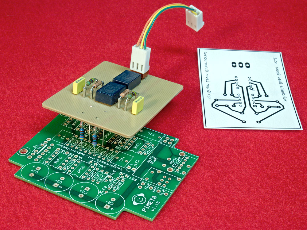
Your relay idea is clever it cuts down on wiring to dpdt switches which is a pain
| Originally Posted by linuxworks /img/forum/go_quote.gif I am allowing for the tangent pcb in many of my builds. a down side is that you need a lot more gain from the amp. but the crossfeed effect is worth having. note that its also worth being able to bypass/disable it. I use relays (of course) 
|
Your relay idea is clever it cuts down on wiring to dpdt switches which is a pain