What and how do we know what IS ‘Better’?
or
It’s all in our heads, or is it?
Part 18 Connector Contact Patch Resistance Reduction
In my experiments and investigations I have looked into the relationship between the ‘size’ of the contact patch in the connectors (RCA & XLR) and the resultant change in signal transfer as it relates to audible changes to the music.
And since I lack the instrumentation necessary to perform ‘proper’ micro-Ω measurements, I must infer that these contact patch enhancements do lower the resistance across the contact of a connector pair.
And it is a fairly ‘safe’ assumption to make where an increase in the surface area of 2 contact patches will reduce the resistance across that mated pair of contacts.
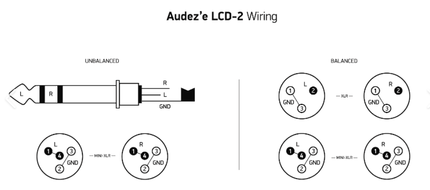
Recently I increased the metal to metal surface contact patch using a silver paste for my 4 pin XLR headphone connector.
There was an immediate change in the presentation of the music. And this was after also noticing changes to the presentation of the music when I cleaned and conditioned that very same connector using Caig DeOxit Gold. And although this initial treatment didn’t increase the contact patch size it did improve the contact patch by removing contaminants and helping to seal the surface of the metal against further oxidation and corrosion.
Another example of increasing the contact patch was when I soldered the wires of a splice in my dedicated branch circuit ac power feed.
This effort resulted in a most welcome change in SQ of the music, especially after I also soldered the ground return wire.
This significantly reduced the resistance and the ability to flow current even though the current draw for this dedicated branch circuit is minimal (120w), which is equivalent to 1 amp of continuous current draw.
I figure the improvement was mostly because the size of the contact patch was increased.
Next is an examination of the connectors themselves, and in general terms, some of their design strengths and weaknesses.
For the ‘line level’ audio signal itself we have 2 main connector types, the RCA and XLR.
And for power the ubiquitous IEC connector on one end and a suitably styled connector for the electrical system in use on the other.
And since there is but one ’standard’ AC connector, no comparison is really possible in this case.
And it should be noted that applying the contact enhancement (silver paste) to the ac power cable connector pins also yield significant improvements as well.
But the signal cable does accord us an interesting chance to test where contact patch increases/reduction in contact resistance, can make an audible difference.
So what are the main differences between the RCA and XLR connectors?
Mostly it’s all about contact patch size, reliability and durability of the connection.
In short RCA connectors are not very ‘robust’, while XLR’s are designed to be used in a variety of commercial applications, where set up and tear down is not just necessary but is done so on a frequent basis. All the while retaining a reliable connection, despite ‘abuse’ of the cable itself.
And one of the reasons for their robustness is the size of the contact patch, but also the design of the mating surfaces themselves, as they tend to ’self clean’, far better than RCA connectors.
But RCA connectors are the standard audio connector and they have come along way from the original design and implementation.
And these days the aftermarket offers some very advanced designs to help improve the reliability and durability of the RCA design from the 40’s.
Quoting Wikipedia…
RCA
“It was originally a low-cost, simple design, intended only for mating and disconnection when servicing the console. Refinement came with later designs, although they remained compatible.
RCA connectors began to replace the older quarter-inch phone connectors for many other applications in the consumer audio world when component high fidelity systems started becoming popular in the 1950s.”
XLR
“Originally manufactured as the Cannon X series, by 1950 a locking mechanism was added (Cannon XL) and by 1955 a version surrounding the female contacts with a synthetic rubber polychloroprene insulation using the part number prefix XLR.”
and this is an interesting bit, here…
“At one time XLR3 connectors were also used extensively on loudspeaker cables, as when first introduced they represented a new standard of ruggedness, and economic alternatives were not readily available.”
IOW XLR connectors have been used as speaker connectors due to their ability to handle greater amounts of current.
And the locking feature of the XLR connector is a clue to its superiority over the RCA connector in that when the connectors are mated they are aligned and held in place in their ideal placement, ie. straight in and not drooping due to the weight of the connector and wire.
This cable droop can significantly alter the contact patch size of RCA connectors as the mating surfaces are no longer in ‘proper’ alignment. And there is no ‘mechanism’ built into these connector designs to insure this degree of ‘proper’ alignment, like the XLR connector has.
But the clincher is the size of the contact patch difference between them.
The RCA does have a single pin in the center to mate up with its counterpart, but even here we see several variations in design of those pins and its mating surface in the female connector.
But the ground connection has an inherent design limitation.
Besides being exclusively a friction/clamping type of connection, the primary contact junction is at the tip of the ground tab ‘ears’ themselves.
And I’m sure there are other designs which increase the size of actual metal to metal contact, but even though it represents the largest surface area for connection, it actually delivers the least.
And that assumes it is plugged straight into its mated connector.
Perhaps a bit of insight can be gained by examining the current and resistance rating of these 2 connectors.
The XLR rating is readily available such as this Neutrik XLR spec
3 pole: 16A
4 pole: 10A
with a resistance rating of ≤ 3 mΩ (that’s 0.003Ω)
Switchcraft provides these specs for their RCA connectors…
Contact Resistance (typical D.O.M.J.):< 0.020 ohms.
(D.O.M.J. Dependent On Mating Jack)
Current Carry @ Working Voltage
(typical D.O.M.J.): 6.0 AMPS.
The difference in contact resistance is an 85% improvement and a 62% increase in current delivery in favor of the XLR connector.
And when silver paste is added those resistance and current numbers should be improved still further.
Another example of improving the contact patch area is by using silver paste on the fuse where it contacts the fuse holder ‘fingers’.
So if I use as an example a typical 5x20mm fuse, which has 4 contact lines per end of the fuse each of which is (I’m guessing here) ≈.2mm in width by 5mm in length. This equates to ≈8mm^2.
So if I add some silver contact paste to those 8 lines and increase their width from .2 to 2mm in width the total surface area for each fuse has increased from 8mm^2 to 80mm^2 or a 10 times increase in the contact patch surface area.
The total surface contact area for this fuse is ≈ 157mm^2 which equates to a change from 5% to ≈ 51% of the available surface area being used after adding the silver paste.
And it should be noted that as the resistance is lowered across the fuse to fuse holder junction, it generates less heat due to lowered Ω across the junction which also means less voltage drop, which also implies greater peak current delivery capacity.
Now granted these changes are small and if the current that passes thru the fuse were more of a steady flow (such as a light bulb or a motor these changes might not make much if any difference especially if the current draw was as small as what my system uses.
But the power supply in our amps and dacs etc doesn’t operate with a steady flow.
Instead it draws current in pulses, which in turn means the amount of current during the peaks of those pulses is higher than 1 amp, and they have a relatively short duration, which is repeated in an ongoing manner.
So really what are the benefits to lowered contact patch resistance, especially in terms of the sonic improvements?
I figure that small signal dynamics and micro-details would be improved, since these are the electrical signals that are most effected by small improvements of lowered contact resistance.
Which means more of the signal is delivered to us, or as I am wont to say “the system gets out of it’s own way” all the more.
And this is what I do hear as a result of paying attention to improving the contact patch of the connections in my system.
JJ :thumb
End Part 19
Next up Auditory memory