ZiShan T1 Hi-Fi Player Thread

Is this the best DAP under $100?

  • Yes

    Votes: 17 23.3%
  • No

    Votes: 20 27.4%
  • Way above the price range!

    Votes: 6 8.2%
  • Could be

    Votes: 30 41.1%

  • Total voters
    73
Sep 16, 2019 at 4:59 AM Post #406 of 652
i want something that fit, not something i have to struggle and break if possible please
is this one good?
https://www.aliexpress.com/item/327...chweb0_0,searchweb201602_3,searchweb201603_52
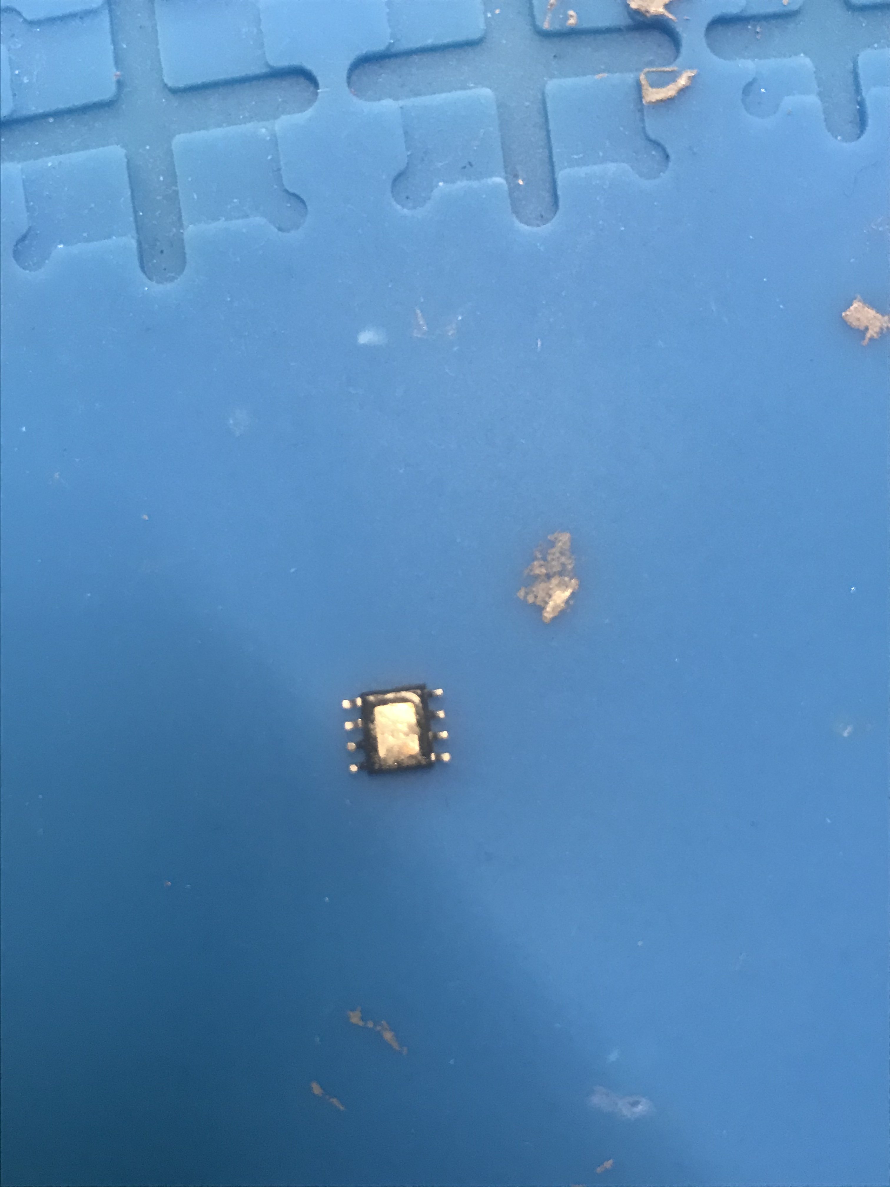
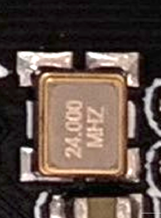
Sorry, not sure about the dimensions, most likely 3.2x2.5, they mention they have 4.TCXO Crystal Oscillator SMD(5*7,5*3.2,3.2*2.5)
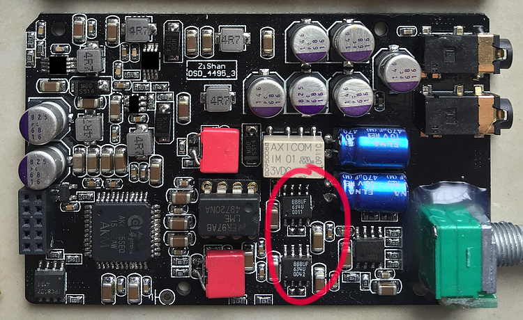
Maybe send them a photo of T1 and ask if they have same size? It also has to have 4 pads (not 6).
But TCXO are even better (and 10 times more expensive) than those that I have, next level up would be femtoclocks, even more expensive :)
Obviously you will be the first one to try these as only handful of people changed their zishan's clocks at all :)
 
Sep 16, 2019 at 5:25 AM Post #408 of 652
AD8397 has will be of no use as there is a transistor output stage after it that feeds 3.5mm output, but removing (bypassing) this stage allows AD8397 drive 3.5mm single-ended output directly.

There’s no removal of anything just a direct line out to the 3.5 by way of the zener diode (that’s what it’s called???) The circuitry still has the same end point which maybe necessary to complete the circuit design and prevent it from shorting and securing a ground.

There’s also NO mention of lowering the resistance like mentioned in previous pages to make the AD8397 work.

Simple mod worth the extra step to put in those wires and before and after AB testing to see if it indeed makes a difference.
 
Last edited:
Sep 16, 2019 at 5:39 AM Post #409 of 652
There’s no removable just a direct line out to the 3.5 by way of the zener diode (that’s what it’s called???) The circuitry still has the same end point which maybe necessary to complete the circuit design and prevent it from shorting and securing a ground.

There’s also NO mention of lowering the resistance like mentioned in previous pages to make the AD8397 work.
Apologies, can you say it again?
I struggle to understand your comment in its current form, but would be happy to help you to understand the circuit and what is happening on the photo.
 
Sep 16, 2019 at 5:49 AM Post #410 of 652
Apologies, can you say it again?
I struggle to understand your comment in its current form, but would be happy to help you to understand the circuit and what is happening on the photo.

Actually let me do the honors, when I pulled off one of my pads, I used the now infamous jewelry wire to connect the positive and negative to power up my caps.

Previously you mentioned that the AD8397 in 3.5m only “works” if you lower the resistance values before even looking out the T1 circuitry (which you don’t own) but keep Putin in your input so you should also mention that you are taking this mod from a second hand source presumably via the internet and don’t have first hand experience in it. This would help your credibility somewhat if you would mention this on the thread instead of lecturing me about how to explain the circuit mod.
 
Last edited:
Sep 16, 2019 at 6:02 AM Post #413 of 652
Previously you mentioned that it only the AD8397 in 3.5 only “works” if you lower the resistance values before even looking out the T1 circuitry (which you don’t own) but keep Putin in your input so you should also mention that you are taking mod from a second hand source presumably via the internet.
Ah, got it.
Let me explain again: in stock T1/DSD 4497 output current is delivered by discrete buffer (voltage followed), which sources its signal from SOIC8 opamp on the main board. So just soldering AD8397 in would not allow it to be high current source for BA’s. Mod on the photo bypasses this buffer, so AD8397 feeds the output directly (via 10ohm output resistors), which could be lowered if necessary indeed.
I cannot comment on your understanding of what I said as I don’t understand it, but happy to help understand what I said, no worries at all!
 
Sep 16, 2019 at 6:06 AM Post #414 of 652
Ah, got it.
Let me explain again: in stock T1/DSD 4497 output current is delivered by discrete buffer (voltage followed), which sources its signal from SOIC8 opamp on the main board. So just soldering AD8397 in would not allow it to be high current source for BA’s. Mod on the photo bypasses this buffer, so AD8397 feeds the output directly (via 10ohm output resistors), which could be lowered if necessary indeed.
I cannot comment on your understanding of what I said as I don’t understand it, but happy to help understand what I said, no worries at all!

Again you are attempting to create your own narrative and answer your own questions.

Also, it’s clear to the thread, that it’s disingenuous to not explain that you don’t have firsthand experience in this specific modification nor own the T1 while using a condescending tone in wanting to somehow explain it to me in a flamboyant way to curry the audience with your extensive knowledge to belittle me or others you don’t seem to like.

There’s no “removing” only a bypass. The words aren’t the same nor synonymous with each other so you can start by explaining what was removed?
 
Last edited:
Sep 16, 2019 at 6:13 AM Post #415 of 652
Again you are attempting to create your own narrative and answer your own questions.

Also, it’s clear to the thread, that it’s disingenuous to not explain that you don’t have firsthand experience in this specific modification nor own the T1 while using a condescending tone in wanting to somehow explain it to me.
Sorry, I thought you were seeking clarification by asking all the questions above?
Because if you were not, then I’m not sure as to what you wanted to achieve?
As for specific modification, I tried AD8397 (among other candidates) and found it harsh and metallic sounding and quite hot (both are most likely due to oscillating), so did not keep it and settled on 1622
There’s no “removing” only a bypass. The words aren’t the same nor synonymous with each other so you can start by explaining what was removed?
Sure, discrete buffer (voltage follower) was removed from the signal flow. In other words, it was bypassed by two wires in the photo (obviously hooked up to DC blocking capacitors output holes, while their input terminals/holes are connected to the buffer’s output, but since capacitors are removed, there is no electrical connection for buffers output, so it is bypassed, removed from the signal flow.
 
Last edited:
Sep 16, 2019 at 6:18 AM Post #416 of 652
Sorry, I thought you were seeking clarification by asking all the questions above?
Because if you were not, then I’m not sure as to what you wanted to achieve?
As for specific modification, I tried AD8397 (among other candidates) and found it harsh and metallic sounding and quite hot (both are most likely due to oscillating), so did not keep it and settled on 1622

What “specific” mod In the T1 are you referring to, mate?

did you attempt this by removing the soldered Opa275 in the 3.5 of what device? Where are those pics from?? Opa1622 in the T1?? Is that the “specific modification” you are talking about.
 
Last edited:
Sep 16, 2019 at 6:29 AM Post #417 of 652
What “specific” mod In the T1 are you referring to, mate?

did you attempt this by removing the solder Opa275 in the 3.5 of what device? Where are those pics from?? Opa1622??? An Ad Hoc??
I’m not your “mate”.
In the same/identical output stage, using AD8397 as subtractor (the function of OP275 in T1) and output driver, as per photo. But no, the photo is not mine as I clearly mentioned it in the original post.
 
Last edited:
Sep 16, 2019 at 8:33 AM Post #420 of 652
Of course they are!
What makes you doubt it?

I have my doubts based on what Fabien posted in a previous post the this thread.

Did you check for yourself in your T1 to confirm just like you you incorrectly stated that in order to use the AD8397 benefits of high current you must remove the resistance or lower them. It doesn’t appear to be the case based on the pic you posted. Can you show where there was a remove of resistance, the digital bjt, caps or zener diodes are removed like you did on the DSD Pro. It’s also important to mention that it’s factually incorrect to say that the DSD Pro and the T1 are the same thing. You seem to keep blurring those distinctions and there’s also a separate thread for the DSD Pro. You also made a posting where you said you seen a DSD Pro with the AD8620 mod in the lpf you did with your DSD Pro on the T1 thread and was equally dismissive about putting the AD8397 in the log in the T1 and walked it back with an insensitive apology when someone else mentioned it you started it as a ”worthwhile” choice for T1.

It’s ok to compare and contrast the two on this thread but it does create misinformation and pollution when you don’t own the device and make general assumptions without verifiable facts.

Simply based on appearance physically they are different in dimensions, microprocessing design and most likely small changes in the DACs. They also have different sound signatures as well!

You would agree that facts are important so can you please double check it since you made those recommendations without owning the actual T2 player before posting.Thanks.
 
Last edited:

Users who are viewing this thread

Back
Top