jl123
100+ Head-Fier
- Joined
- Nov 26, 2005
- Posts
- 291
- Likes
- 11
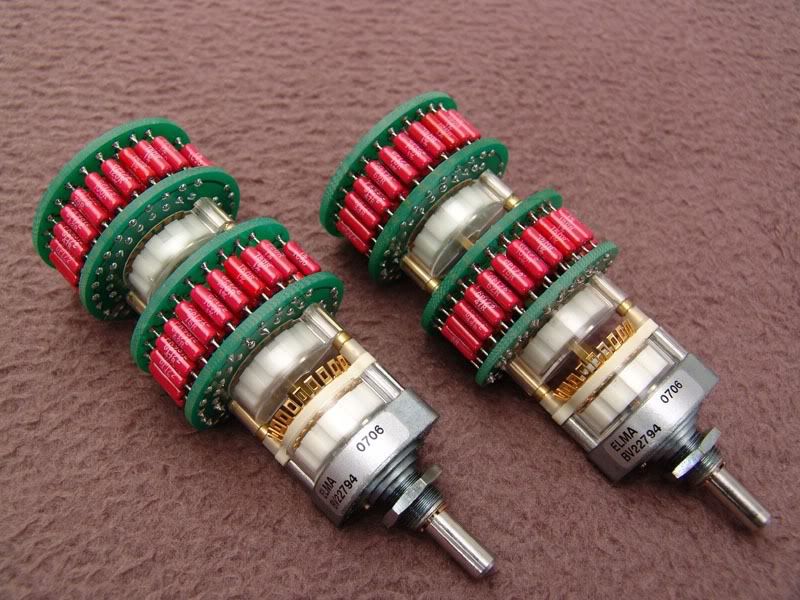
Very nice!
May I ask what camera you have?
 You have great light in that room lol.
May I ask what camera you have?
| Originally Posted by Karlosak ...and the winner is: MASantos! Congratulations! 
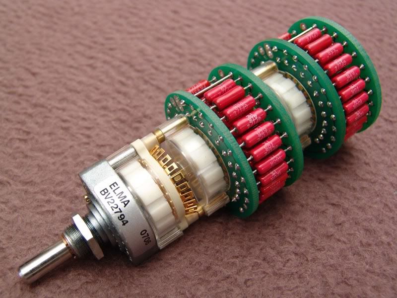
jarthel, if I wanted something "custom made" in your truest sense of word, I would have to take 100+ switches just to ensure ELMA would even speak with me and moreover be quite a wealthy man! For me it's satisfying that these switches aren't in the ELMA's catalog 
ilikepie, waffer was a typo, should be wafer. It's one of those green widgets 
|

| Originally Posted by Todd R Have fun soldering. I built one of those last year and it took a couple days to complete. Should keep you out of trouble for a while
|
| Originally Posted by bperboy Nah, he'll probably be so excited to finish the shiny new attenuator that he'll pull an all-nighter!
|


| Originally Posted by Andrea All this mess because you don't want traditional volume pots? I've never had the slightest problem with them, nor they've ever seemed a bottleneck.. |

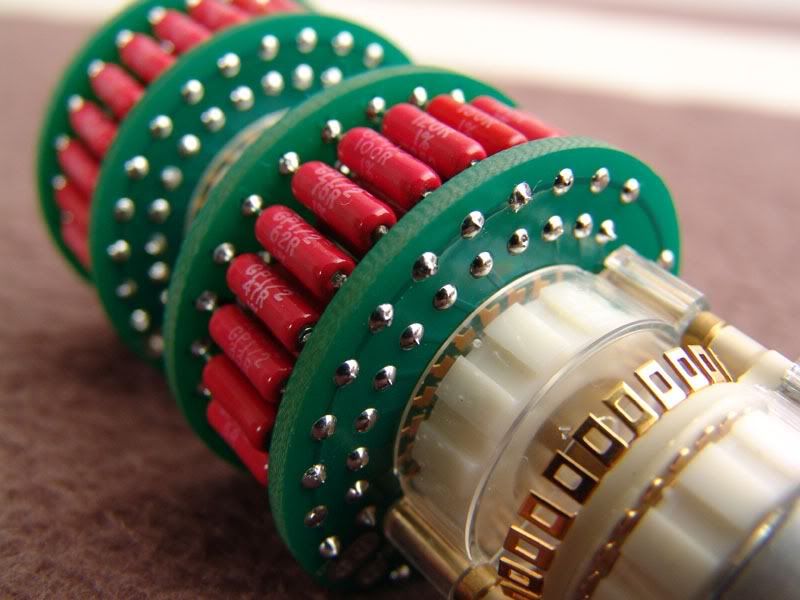


| Originally Posted by mb3k Wow, that's a spot on job! Looks like it has been soldered by a machine
|
| Originally Posted by MASantos where's the schematic for the led volume display?
|
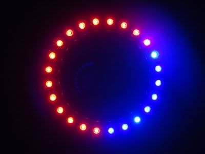
| Originally Posted by phergus_25 Any shots of it below full volume? |
