y1 gamma-1 DAC
Mar 25, 2010 at 8:02 PM Post #1,261 of 1,546
Quote:

Originally Posted by amb /img/forum/go_quote.gif
If you mean config E (S/PDIF only), yes.


Exactly what I meant...

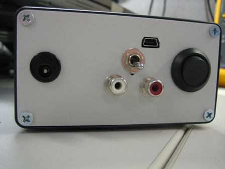
The analog output is a 3.5mm stereo phone jack, correct?
Do they sell a male 3.5mm stereo phone jack to 2 wire (White/Red) RCA jack wire?
 
Mar 29, 2010 at 10:39 PM Post #1,264 of 1,546
Hi to everyone,
I'd like to build a gamma1 lite but there's a few things that i don't know.
I've done a lot of soldering but only few times smd, how many smds are in the gamma1? Is difficult to assembly?
If i buy the pieces on the amb store, how can do the list for the lite version if I don't know the exact bom for the lite?? I'm not interested to the case but only the fundamental pieces.
I'm so confused
ph34r.gif

Thanks to those who help me
smily_headphones1.gif
 
Apr 6, 2010 at 12:37 AM Post #1,266 of 1,546
ok guys so i re did my y-1, but i am still getting the same problem.
usb device not recognized..
frown.gif
i figure it is my u1 again.. to my eye and my 40X loupe, i don't seem to see any bridges or anything suspect.. but here are some pics with a better camera. http://imgur.com/NEhrM.jpg see anything bad?
I am getting the correct voltages at 3.3 and 5v testing points..
2nd crack at the usb receiver.. hopefully I can figure it out this time
 
Apr 6, 2010 at 7:03 AM Post #1,271 of 1,546
omg.. i lifted those resistors off the other gamma-1.. so maybe it wasn't my U1!!
all along turns out it was the 22ohm resistors! w/ colonel mustard in the kitchen w/ the revolver..

looks like i've got another excuse to order more parts from mouser..
smily_headphones1.gif
thanks misterx.. you've been instrumental in my amb builds. i really appreciate it.
will check in when i finally get it working...
 
Apr 8, 2010 at 4:28 AM Post #1,272 of 1,546
Hey everyone!

I've been here a little while, but this is my first post so to start I want to thank AMB and Misterx for their hard work and a great DAC!

So now to my problem. I've put together a y1 Full ++ to be connected to a y2. Since I dont have all of the parts for the y2 yet, I just connected the wires together like noted on the website and plugged it into the computer. everything looked okay, and the voltages all looked good, but no music played. I unplugged it and looked it over and realized i made a pretty dumb mistake in my haste and connected the data wire from the usb board to pin 4 rather than pin 5 on the J5D of the DAC board. I put it back where it should be, but stil, no music, led never goes green, and DAC doesnt work with optical either (no coax to test, no external power yet either. Did I royally mess something up? Thanks for the help!
 
Apr 8, 2010 at 4:41 AM Post #1,273 of 1,546
I don't think that error should have caused any damage, but that's just a guess.
Check to make sure all your jumpers are set correctly,and check all solder joiints.
Does the computer recognizes it as a "USB audio DAC"? Where exactly did you check the voltages and what did you read on your meter?
 
Apr 8, 2010 at 4:48 AM Post #1,274 of 1,546
Quick reply!
smily_headphones1.gif
Jumpers should be set correctly (JP1U 1-2 shorted), and from what I can see the solder joints are okay (I am a newbie at this tho, so who knows.) The PC did recognize it as a USB audio DAC. I tried switching to it and use it as default, but no dice. I am unable to check the voltages again, but from memory, the 5v was ~5.04 or 5.07, the 3.3 was very close to that, but the 4.5v was 4.73v.
 
Apr 8, 2010 at 5:00 AM Post #1,275 of 1,546
ok, the voltages are fine. You got 4.73V rather than 4.5V because you used a TPS793475 regulator instead of LP2985A-4.5.
The fact that the computer recognized it as a USB audio DAC is good, that means at least the USB side of the PCM2707 chip is good. Since it also doesn't work with optical input, then chances are the problem is either with the CS8416 or WM8501 chips. Examine your solder joints carefully on these chips, using a loupe or other magnifier. With the power off, check each joint with your DMM in ohms mode, between the pin where it comes out of the chip, and the edge of the solderpad (or some other point of the circuit where it's supposed to connect to). If necessary use the schematic diagram as your guide. Reflow any joint that doesn't read near zero ohms. Also check adjacent pads for solder bridges (except where the pads should be connected, again -- see the schematic).
 

Users who are viewing this thread

Back
Top