


wushuliu
100+ Head-Fier
- Joined
- Jun 24, 2009
- Posts
- 493
- Likes
- 152
Quote:
Ok, I'll give a shot at reflowing solder joints. My source is direct from a WDTV optical out and downstream is a B1 buffer to Class D amp... I have other inputs going through the B1 and they work fine, so it's probably solder joints as youve said...
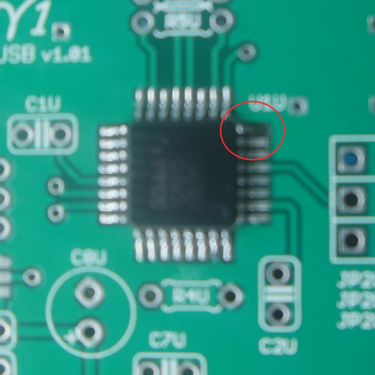
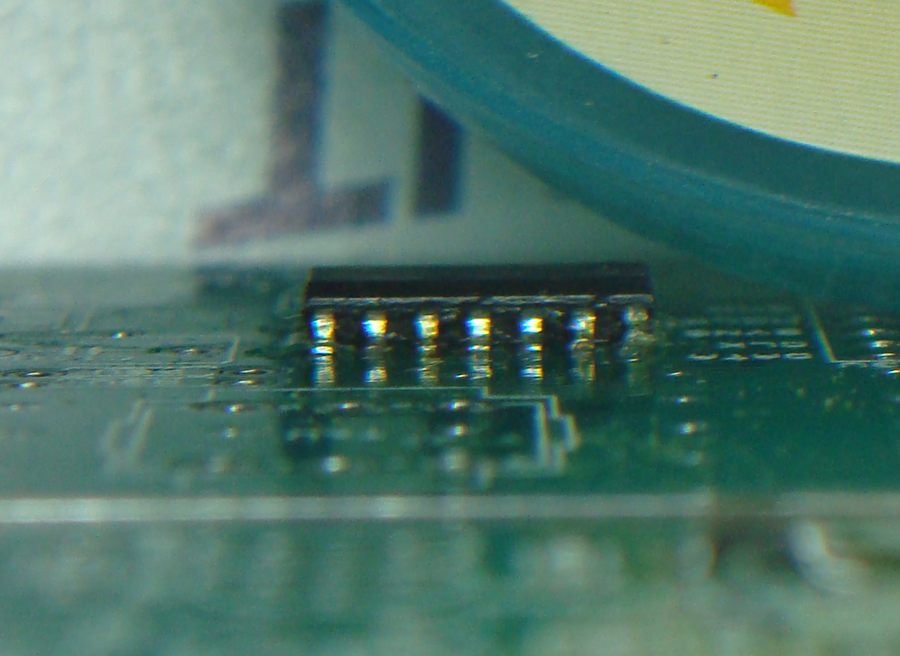
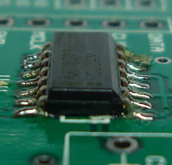
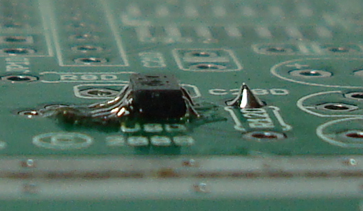
| Originally Posted by amb /img/forum/go_quote.gif wushuliu, the two things are most likely separate problems. The LED not lighting up is probably due to a solder joint problem at U2D, U8D, Q1D, Q2D, R11D, R12D or R13D. For the crackly noise problem, try reflowing the solder joints at U3D. If that doesn't fix it, make sure your S/PDIF source is putting out a clean signal (i.e., no clipping) to begin with. Maybe it's a software configuration problem or simply a bad recording. Lastly, what are you using as your source and what is the rest of the audio chain downstream of the γ1? |
Ok, I'll give a shot at reflowing solder joints. My source is direct from a WDTV optical out and downstream is a B1 buffer to Class D amp... I have other inputs going through the B1 and they work fine, so it's probably solder joints as youve said...

