Howdy,
I made a thread already, however I didn't realize there was a dedicated thread for the y1. I'll just post here.
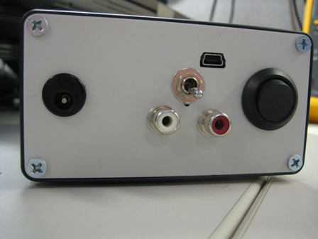
I have picked out parts for my y1, which is just a toslink in, and I am going to hardwire the audio out to my minimax. The case is going to be one of those plastic containers you put leftovers in, however I am planning on buying a large case eventually.
1.) Since I am using a plastic container would I need to ground anything? Should I just man up and buy a case?
2.) I only want one input, is it possible to skip the "NKK G13JVCF bicolor illuminated toggle switch"? From what I understand that switch is used to toggle the inputs. Would I need to solder jumpers to my board to skip this switch?
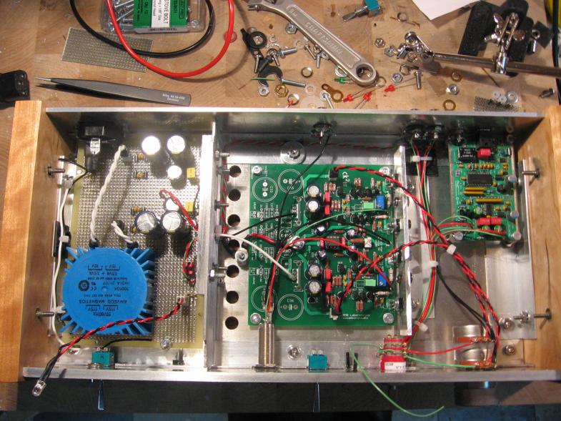
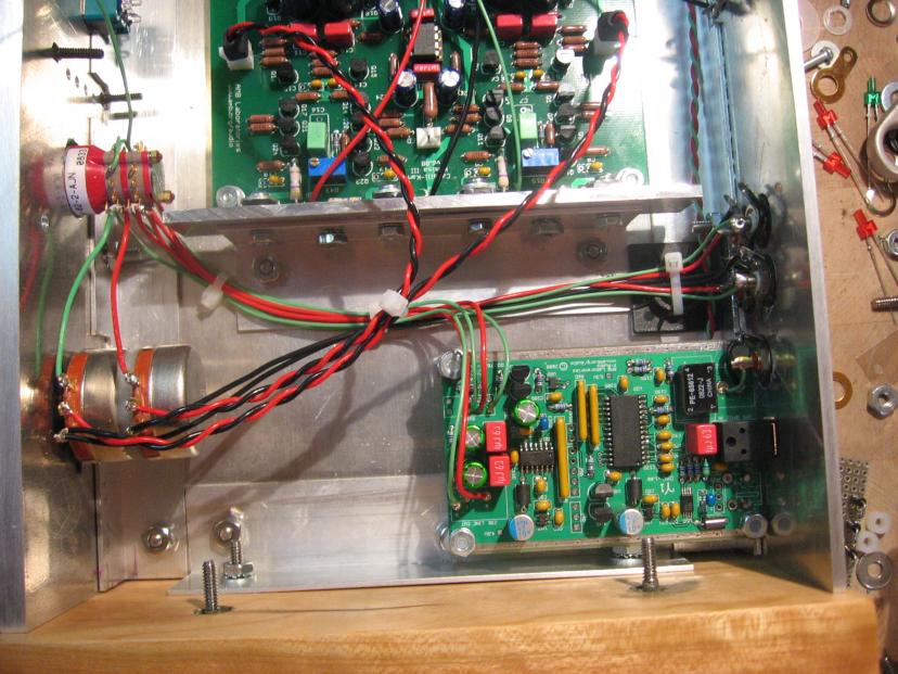
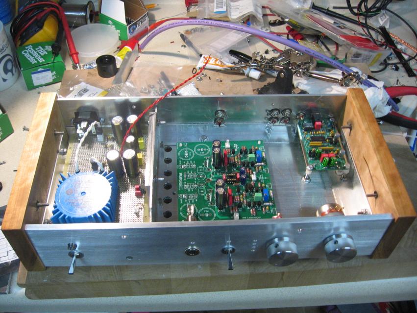
3.) I've decided to build the σ24 and σ25 kits as well. I think all of the Molex input and output terminals have the wrong pictures in the Mouser Website. Is that correct? I can just skip these and solder directly to the board right?
4.) Can I just cut an existing power cord and use that for the input?
5.) I just noticed that there weren't any fuses installed. Can I add fuses?
6.) Why can't the "Pulse BV030-7151.0 1.5VA EI-30" be used on the both the y1 and y2?
Sorry about all the questions, but I am no electronics engineer. Any help would be appreciated. Also, if you can only answer a couple of these, then please share your knowledge.


")

