y1 gamma-1 DAC
Dec 31, 2009 at 3:57 AM Post #1,051 of 1,546
Quote:

Originally Posted by PScal /img/forum/go_quote.gif
Did you use the WM8741 or WM8742 DAC on your gamma 2? If so, U6 should be omitted (see note 1 on the gamma 2 parts list). However, if you used WM8740, you are ok
wink.gif


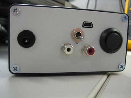
That is a good point because if he is using an 8740 part then why does he have a Filter switch? The 8740 does not have selectable filters.
 
Dec 31, 2009 at 4:28 AM Post #1,053 of 1,546
U6 would not make the DAC not work.

The only top side picture of the Gamma 2 is taken at an angle that doesn't really allow us to see U1.

Top down images tend to work a little better...
What I do is stand the board on it's edge, set the camera down on the table, disable the flash, enable macro mode and then snap the picture.

Here is an example---->

http://i23.photobucket.com/albums/b3...e/DSC00505.jpg
 
Dec 31, 2009 at 4:38 AM Post #1,054 of 1,546
Are there any photos you'd like me to take specifically extra? I.E. Highligting any part of the board?
Read your post, uploading pictures of the gamma2 U1 and U2 specifically.

Another question: Do both holes @ J3 need to goto the other two holes JP1D? Or is it just pin 2 of JP1D to the corresponding at J3?
 
Dec 31, 2009 at 5:18 AM Post #1,056 of 1,546
See how much better that works?
biggrin.gif


Put you meter in ohms mode and measure between the top of the crystal and each one of the through hole pads on the Gamma 2 board (the solder on the crystal appears to be piled up awfully high).

Quote:

Another question: Do both holes @ J3 need to goto the other two holes JP1D? Or is it just pin 2 of JP1D to the corresponding at J3?


Actually reading the instructions FTW.

Quote:

•If your γ1 is the Full (A), S/PDIF-only (E) or Full++ (F) configuration, then the "leftover" pin from the supplied SIP-9 header should be installed in γ1's JP1D pin 2 (round pad), to mate with the matching receptacle at γ2's J3 (see picture below).


leftoverpin.jpg
 
Dec 31, 2009 at 5:18 AM Post #1,057 of 1,546
Quote:

Originally Posted by mattcalf /img/forum/go_quote.gif
ADo both holes @ J3 need to goto the other two holes JP1D? Or is it just pin 2 of JP1D to the corresponding at J3?


Only pin 2 needs to be connected, although no harm done if you connect both pins.
 
Jan 2, 2010 at 6:50 AM Post #1,058 of 1,546
After having the parts but not doing it for nearly 3 months, I decided to use my holiday vacation to attempt building the gamma 1. Well I've found out that if you do it right, SMD soldering isn't too bad. But once you mess up, it can quickly get frustrating. I have most of the SMD parts done (and hopefully not fried :p
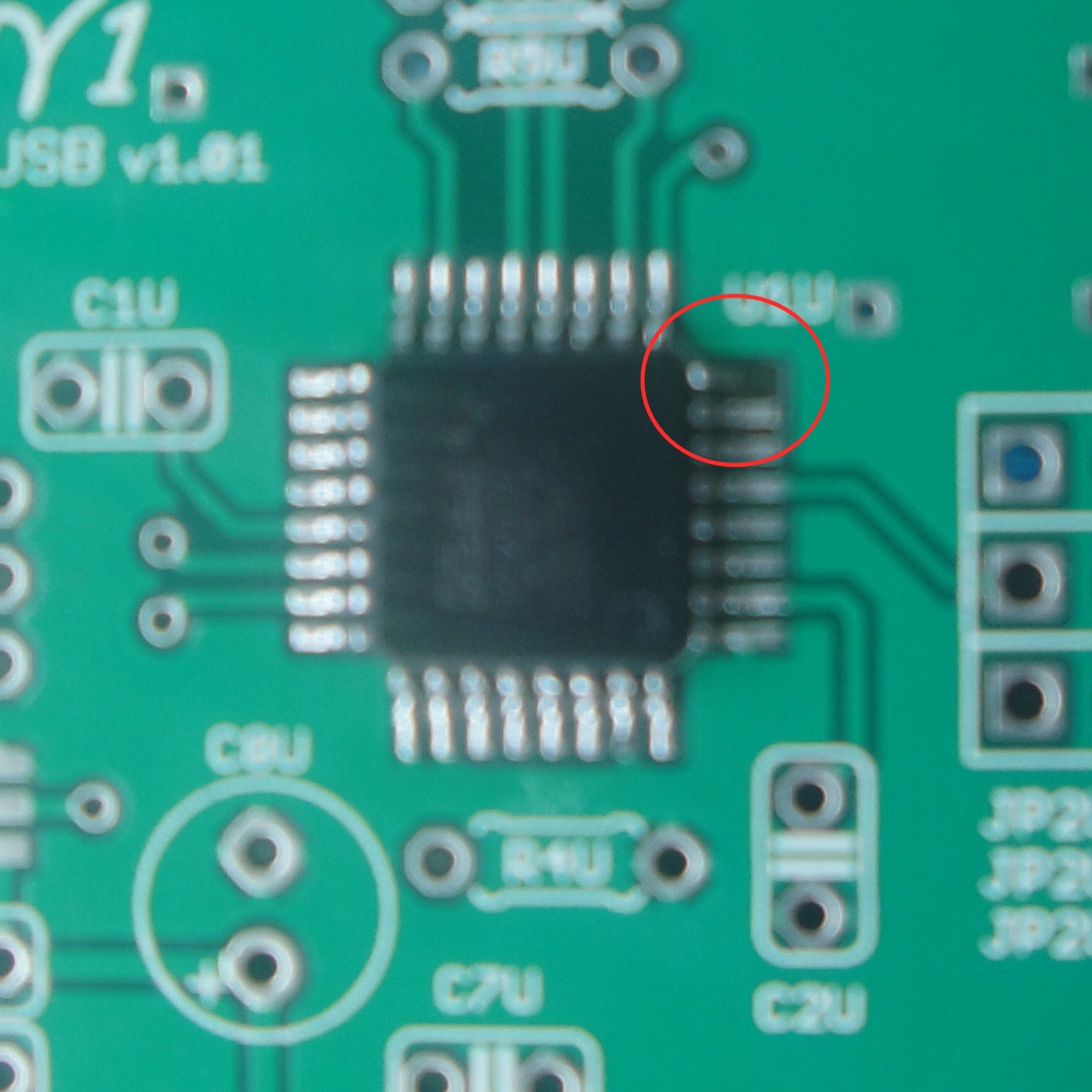
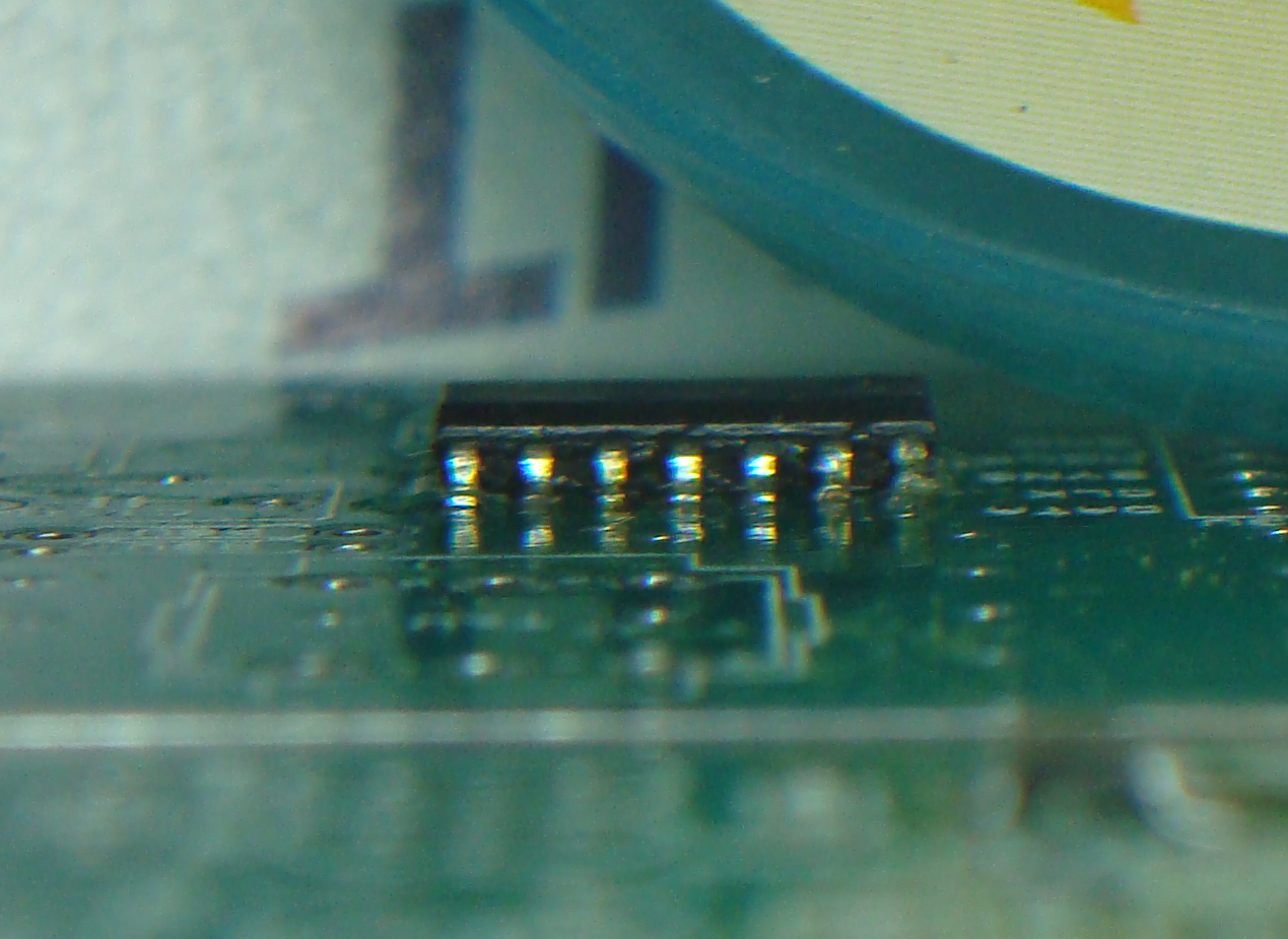
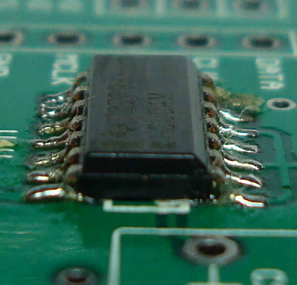
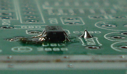
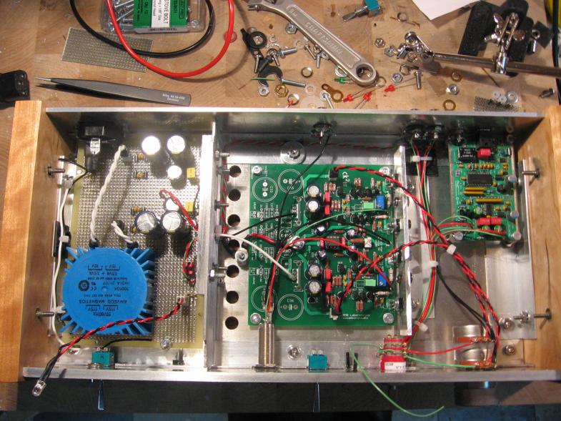
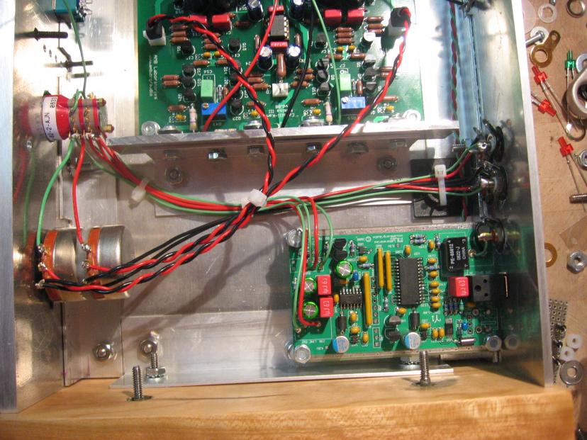
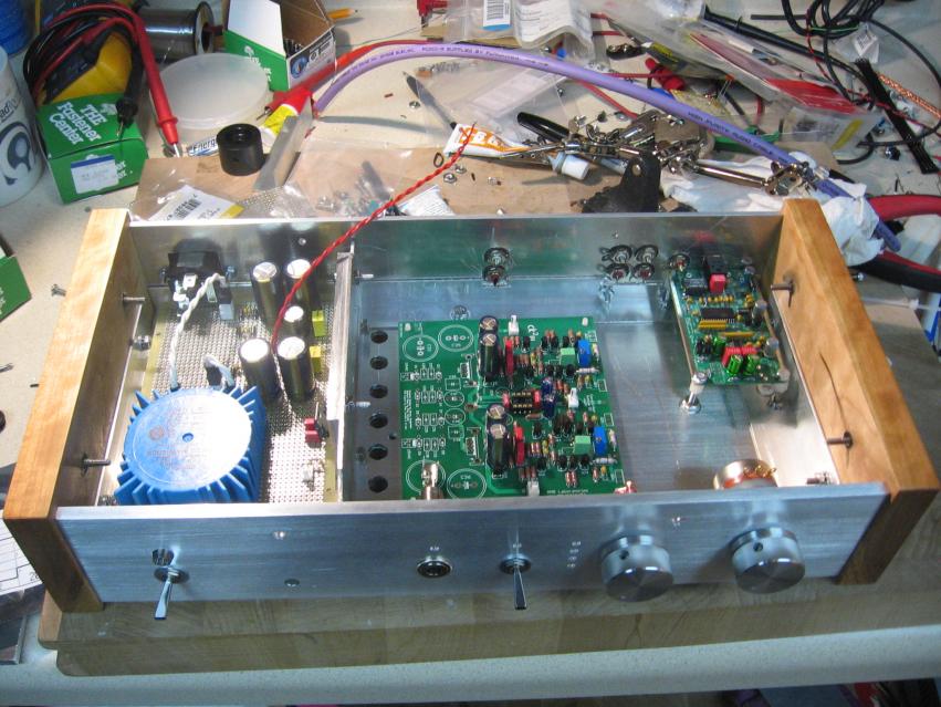
), but there are a few places where I have bridges connecting pins. Any tips on fixing that?

I thought that perhaps solder wick might be the best solution, but it's not really cooperating like I'd like it to. More specifically, the solder underneath seems to take forever to melt and I'm hesitant to hold the iron down for a long time.

Also, I think I may be missing a cheap part (R7D a resistor network), but I'll worry about that after I get the SMD stuff done, since I'll probably start becoming busy with homework again, anyways.
 
Jan 2, 2010 at 6:58 AM Post #1,059 of 1,546
Quote:

there are a few places where I have bridges connecting pins. Any tips on fixing that?


Add flux, heat both pins and then wick it away with a quick stroke of your soldering iron.

Another one is.. take a break when you find yourself becoming frustrated.
 
Jan 2, 2010 at 4:42 PM Post #1,060 of 1,546
I just completed building my first y1. It was my 2nd project after a psu. I realized that I had misaligned the square PCM2707 chip too late after 2 sides where soldered on. Removing it was frustrating! After several failed attempts with flux, solder and the iron I finally fluxed both sides, put the board on its side, heated it with a creme brulee' torch while pushing against the chip. It popped off easily.

I though I had fried the chip with all the heat, but after carefully soldering back in it now works flawlessly and sounds great!

Tip is to be very careful soldering those smb components.
 
Jan 2, 2010 at 4:56 PM Post #1,061 of 1,546
Quote:

Originally Posted by francisdemarte /img/forum/go_quote.gif
I just completed building my first y1. It was my 2nd project after a psu. I realized that I had misaligned the square PCM2707 chip too late after 2 sides where soldered on. Removing it was frustrating! After several failed attempts with flux, solder and the iron I finally fluxed both sides, put the board on its side, heated it with a creme brulee' torch while pushing against the chip. It popped off easily.

I though I had fried the chip with all the heat, but after carefully soldering back in it now works flawlessly and sounds great!

Tip is to be very careful soldering those smb components.


Wow glad that worked! Good job with the torch.
 
Jan 3, 2010 at 5:42 AM Post #1,063 of 1,546
Quote:

Originally Posted by francisdemarte /img/forum/go_quote.gif
I just completed building my first y1. It was my 2nd project after a psu. I realized that I had misaligned the square PCM2707 chip too late after 2 sides where soldered on. Removing it was frustrating! After several failed attempts with flux, solder and the iron I finally fluxed both sides, put the board on its side, heated it with a creme brulee' torch while pushing against the chip. It popped off easily.

I though I had fried the chip with all the heat, but after carefully soldering back in it now works flawlessly and sounds great!

Tip is to be very careful soldering those smb components.


Awesome
smily_headphones1.gif
 
Jan 5, 2010 at 8:28 PM Post #1,064 of 1,546
Thanks! You should try my Creme Brulee'
smily_headphones1.gif


Here's where I got the idea from:

How to De-Solder surface mount ICs

Secret is keep the torch at distance, keep it moving, try to heat only the pins, and flux...lots of it. If I had Chip Quick on hand I'd use it but I didn't and I was at wits end.

Anyway thanks to Ti and everyone who contributed to this forum my Gamma2 is up and running and sounds fantastic!
 

Users who are viewing this thread

Back
Top