woot! I got my CMoy kit in the mail today!
Mar 18, 2007 at 6:06 AM Thread Starter Post #1 of 66

Joshatdot

Headphoneus Supremus
Joined
Jan 30, 2007
Posts
2,960
Likes
12
Location
Anacortes, WA USA
Thanks soloz2 for the kit!

Now I just need to visit Radio Shack to get the Protoboard and wires! Too bad they are closed now
frown.gif


I would have taken more pix but battery ran out. I think I'll use the Altoids Dark Chocolate Dipped Mints Tin. I am going to use the Burr-Brown OPA2227PA Op-Amp. Not sure on what type of Virtual Ground Circuit I'll use, what is best & EZ'est to make?

dscn15171wn8.jpg

dscn1518sv3.jpg
 
Mar 18, 2007 at 6:27 AM Post #3 of 66
Quote:

Originally Posted by colonelkernel8 /img/forum/go_quote.gif
Better yet, get a PCB made instead of using a protoboard. Will make everything a lot nicer looking.


Ohhh...how do I do that? how much?
 
Mar 18, 2007 at 6:00 PM Post #6 of 66
I am sure someone would be willing to make one for you for little or nothing on the forum here, just ask around.

I can get you the traces and eagle file if you'd like. Keep in mind that this cmoy will require a railsplitter too, so you may have to order that, unless the person who is making your board happens to have an extra lying around that they can throw in.
 
Mar 18, 2007 at 10:03 PM Post #7 of 66
Quote:

Originally Posted by colonelkernel8 /img/forum/go_quote.gif
I am sure someone would be willing to make one for you for little or nothing on the forum here, just ask around.

I can get you the traces and eagle file if you'd like. Keep in mind that this cmoy will require a railsplitter too, so you may have to order that, unless the person who is making your board happens to have an extra lying around that they can throw in.


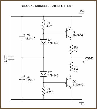
One if these?: I don't remember what type soloz2 sent me.

sijosae.png
 
Mar 18, 2007 at 10:20 PM Post #8 of 66
I think he means a TLE2426. Hard to tell where it would go on that board layout without the schematic.

EDIT: Looks like it would go right in the center of the board below the dip socket.

The original Cmoy layout uses a simple resistor divider to create the virtual ground. The circuit diagram you posted and the TLE2426 will be much more stable and accurate.

Tangent has a page describing many ways to create a virtual ground.
http://www.tangentsoft.net/elec/vgrounds.html
 
Mar 19, 2007 at 12:24 AM Post #9 of 66
I am looking thru the parts list soloz2 sent me, I think it is the diagram I posted above, but with a dc power jack for recharging.

Here is the PM he sent me:

Quote:

Originally Posted by soloz2
I have everything you need except for a couple parts you can pick up from radio shack.

upgraded caps, switchcraft jacks, vishy dale resisters, pot and even vol. knob. I also have diodes for a simple battery charge circuit.

the only parts I don't have on hand are:

- switched dc jack for battery charge circuit
- battery holder
- proto board

all 3 of these parts can be had for cheap from radioshack.


Here is what is on the parts list:
C1 - 2x 470µF 35v cap
C2 - 2x 0.22 µF Polypropylene cap
R1 - 2x 4.7 KΩ 1/4W
R2 - 2x 100 KΩ 1/4W
R3 - 2x 2.0 KΩ 1/4W gain of 6 resister
R4 - 2x 10 KΩ 1/4W
RLED - 1x 4.7 KΩ 1/4W
D1 - Blue LED
IN/OUT - 2x 3.5mm Stereo Jacks
OPA - 1x OPA2277PA-ND

1x DIP-8 IC Socket
1x Alps 10K RK097
1x black aluminum volume knob
1x LED T1 mounting clip
2x battery charging diodes
 
Mar 19, 2007 at 2:14 AM Post #10 of 66
Looks like a standard Cmoy circuit. The R1 resistors are for the resistor divider.

If you find two transistors (2n3906/2n3904) and two small signal diodes (1n4148, little glass ones, usually red with a black band on one end), then you probably have the parts for the discrete voltage divider. (You can get these at Radio Shack too). Two 10ohm resistors too.

To make a battery charger you also need a lm317 regulator. Check out this thread: http://www.head-fi.org/forums/showth...ht=nimh+charge

I wouldn't worry about the charger and just build the Cmoy. You can add the charger later.

OPA2277 is an unusual choice. More common is the OPA2227. From the datasheet the OPA2277 should work well on battery power.

Half the fun is trying different op-amps.
 
Mar 19, 2007 at 2:27 AM Post #11 of 66
yeah, it's the basic cmoy design with better caps and vishy dale resisters. The virtual ground is made with R1. I too would suggest building the basic circuit to begin with and you can add a charging circuit later (diodes included for a simple charging circuit)
 
Mar 19, 2007 at 2:41 AM Post #12 of 66
Quote:

Originally Posted by achina /img/forum/go_quote.gif
Looks like a standard Cmoy circuit. The R1 resistors are for the resistor divider.

If you find two transistors (2n3906/2n3904) and two small signal diodes (1n4148, little glass ones, usually red with a black band on one end), then you probably have the parts for the discrete voltage divider. (You can get these at Radio Shack too). Two 10ohm resistors too.

To make a battery charger you also need a lm317 regulator. Check out this thread: http://www.head-fi.org/forums/showth...ht=nimh+charge

I wouldn't worry about the charger and just build the Cmoy. You can add the charger later.

OPA2277 is an unusual choice. More common is the OPA2227. From the datasheet the OPA2277 should work well on battery power.

Half the fun is trying different op-amps.


Yeah I asked for a OPA2227PA in my WTB post. I'll take a closer look at the chip itself. What are the differences between the 2277 and 2227?
 
Mar 19, 2007 at 3:16 AM Post #14 of 66
Two different families of op-amps.

OPA227 Single
OPA2227 Dual
OPA4227 Quad

OPA277 Single
OPA2277 Dual
OPA4277 Quad

They really couldn't make it any more confusing.

The OPA2277 has only 1Mhz bandwidth vs the OPA2227 which has 8Mhz. I do not know how it sounds. Theoretically 1Mhz should be enough for audio. The stock OPA2132 is 8Mhz.
 
Mar 19, 2007 at 3:49 AM Post #15 of 66
RadioShack board is just as compact as a printed board and using it will be a little more educational. My first 2 CMOY circuits looked like crap, but I planned my 3rd a little better and it looks really neat. Seating the components (especially the caps) flush to the board is the key.
 

Users who are viewing this thread

Back
Top