Why did my capacitors blown?
Oct 21, 2007 at 9:03 AM Post #17 of 46
Quote:

Originally Posted by Wotan1 /img/forum/go_quote.gif
primary electrolytic capacitors


there are two sets of caps in it. The first set are rail to rail caps for the buffers and the another set which are rail to ground for the opamps. You'd have to find out what which set they're referring to.

Quote:

Originally Posted by holland /img/forum/go_quote.gif
Which caps blew? The 100uF/20V rail to rail caps?

I don't believe the LISA III has a built in voltage regulator for the power rails. If the schematic I am looking at is accurate, it is indicating a 20V cap, then the problem is there. Increase that to 35V rating.

Please measure the rail to rail voltage when you plug in the adapter. Maybe there's a regulator in the triad design to control rail to rail voltage. If so, it's possible the regulator is bad.


The 20V caps should not be bursting as they are connected rail to ground.(two caps in series)They should have double the voltage tolerance this way.

There is no regulator to control the rail to rail voltages. Only the TLE2426 is used for rail splitting. However, if the 20V caps are bursting that will only mean that there's something wrong with the splitter. On the other hand, the only regulator inside the LISA III is configured as a constant current source (LM337) to trickle charge the batteries
smily_headphones1.gif
 
Oct 21, 2007 at 9:30 AM Post #18 of 46
Quote:

Originally Posted by flashbak /img/forum/go_quote.gif
Wotan1,
Your best bet is to contact Phil LaRocco about this issue!!!! He knows the amp and design better then anyone!!


Thanks. I'm touch with him and he repaired the amp the first. He says it was tested good when it was shipped and I trust him on that. He says that that adapters are at fault. However I cannot see why 2 different adapters the could have caused the same problem. And checked and dubble checked to make sure I was doing everyting right re voltage and polarity.
 
Oct 21, 2007 at 9:42 AM Post #19 of 46
I seems that Phil prefers a linear and switching adapter. Not sure about the Ansmann. Could not find any related specs. If it's not linear and switching, could that have caused the problem.

What about a plug not fitting well. Could that cause a short circuit? I'm getting sparks when connecting the adapter to the dead amp.
 
Oct 21, 2007 at 9:45 AM Post #20 of 46
Quote:

Originally Posted by TzeYang /img/forum/go_quote.gif
there are two sets of caps in it. The first set are rail to rail caps for the buffers and the another set which are rail to ground for the opamps. You'd have to find out what which set they're referring to.


The 20V caps should not be bursting as they are connected rail to ground.(two caps in series)They should have double the voltage tolerance this way.

There is no regulator to control the rail to rail voltages. Only the TLE2426 is used for rail splitting. However, if the 20V caps are bursting that will only mean that there's something wrong with the splitter. On the other hand, the only regulator inside the LISA III is configured as a constant current source (LM337) to trickle charge the batteries
smily_headphones1.gif


I will see if I can open the amp. It's the XP with battery pack, so it's a bit different compared to the standard Lisa.
 
Oct 21, 2007 at 1:19 PM Post #21 of 46
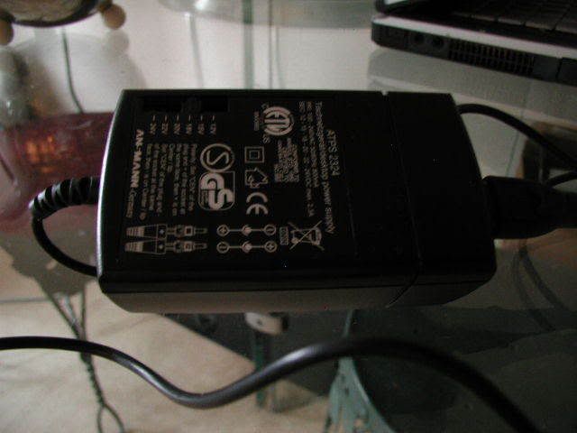
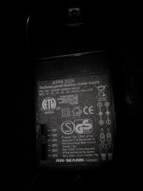
Please post a picture of the adapter you're using.

I am some what surprised to learn that the vendor is selling an amp without a power supply.
 
Oct 21, 2007 at 1:22 PM Post #22 of 46
In the schematic there are three 20 V 100 uF electrolytic caps (blue OS-CONS) going from rail to rail (+ to -) and six 100 uF 16 V caps going from rail (+ and -) to ground.

What caps did blow? If it's the 16 V's, it could be like TzeYang said, the TLE2426 railsplitter is fried. If it's dead it could split like 2/22 V instead of 12/12.

I've constantly used a regulated 24 V supply to my LISAIII clone with 20 V 100 uF OS-CONs, and I've never blown a cap. I've used 24 V to 16 V electrolytics without blowing anything. I've blown some tantalums spec'd to 35 V with 18 V supply. Are there tantalums in the amp? Are you sure there's nothing fishy with your PSU?
 
Oct 21, 2007 at 1:42 PM Post #23 of 46
Quote:

Originally Posted by NelsonVandal /img/forum/go_quote.gif
In the schematic there are three 20 V 100 uF electrolytic caps (blue OS-CONS) going from rail to rail (+ to -) and six 100 uF 16 V caps going from rail (+ and -) to ground.

What caps did blow? If it's the 16 V's, it could be like TzeYang said, the TLE2426 railsplitter is fried. If it's dead it could split like 2/22 V instead of 12/12.

I've constantly used a regulated 24 V supply to my LISAIII clone with 20 V 100 uF OS-CONs, and I've never blown a cap. I've used 24 V to 16 V electrolytics without blowing anything. I've blown some tantalums spec'd to 35 V with 18 V supply. Are there tantalums in the amp? Are you sure there's nothing fishy with your PSU?


Guys,

Ok, this may sound stupid I finaly opened the amp (this was more easy than I initially thought) and was somehow surprised to see that everything inside looked normal. I would have expected some fried stuff in there, but nothing strange or to my eye out of order. Could it be that history while repeating it self and came out with a different outcome. I'm not going to post the pics. I've send them to TzeYAng, will send them to you as well.
 
Oct 21, 2007 at 2:05 PM Post #24 of 46
Quote:

Originally Posted by n_maher /img/forum/go_quote.gif
Please post a picture of the adapter you're using.

I am some what surprised to learn that the vendor is selling an amp without a power supply.


As requested and thanks for helping..

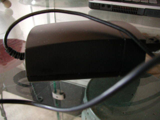
P1010247.jpg


P1010248.jpg


P1010254.jpg
 
Oct 21, 2007 at 2:44 PM Post #25 of 46
Do you have access to a multi meter?

The reason that I ask is that if you do I would suggest the following: carefully measure the output voltage of the wallwart when setup with what you think will produce the "center pin positive" condition. From the pictures it looks like you can change this setting for the wallwart, which is something I haven't seen before and looks like it would be easy to get backwards. There are two reasons to take this measurement, one to check the polarity and make sure that you're doing it correctly, two to check the unloaded output of the wallwart. Given that the wallwart is rated for 800mA on the 24V output (at least that's how I read the label) you may very well find that at the lower settings it is still outputting well over 24VDC. The reason for this higher output is that the LISA is probably drawing less than 250mA at idle so there's pretty large excess of capacity that translates into more voltage.

If the rail-to-rail capacitors are only rated for 20V it would seem very unwise to me to use anything higher than say a 12VDC supply. I've seen 12V supplies output well over 15V when lightly loaded and I always like to have a little headroom left over. I found a couple of pictures on Phil's site in which it's pretty clear that the caps are 20V rated and that's what they are spec'd at in the schematic that I found as well. I am a bit surprised that Phil and the builder would do this since even if the amp was configured to run off of 9V batteries you could still easily see over 20V across C4. A fair number of 9V rechargables run over 10V on a full charge and unless I'm reading the schematic wrong (definitely a possibility) C4 sits across both rails and would see the full power supply voltage. Someone please confirm this as I'm operating at the bleeding edge of my capabilities here.

Link to LISAIII schematic as posted by the manufacturer, so I'm assuming it's safe to share.
 
Oct 21, 2007 at 2:48 PM Post #26 of 46
I can see no blown components at all. Exactly what is the problem. Is it totally dead? No sound? Faulty sound?

Very strange, I can't see any battery connectors on the board. How do you connect the batteries? Have you tried the amp with two non-rechargable batteries (if you do, do NOT connect the PSU).

Can it be the DC connector that's bad. There's a switch in it, switching the batteries for charge or load when plugging in/out the DC-plug. Or can it be the on/off switch that's bad.

Since you have a multimeter, you could do some measuring to see where the power dies, but if you do, be very careful not to short anything. You could measure on the jack, switch and on one of the three larger caps, just to see where there's power.

But... this is a very expensive amp, and whatever you do, you risk to void your warranty, and I really think that this problem should be fixed by the manufacturer.
 
Oct 21, 2007 at 3:12 PM Post #27 of 46
Quote:

Originally Posted by n_maher /img/forum/go_quote.gif
Do you have access to a multi meter?

The reason that I ask is that if you do I would suggest the following: carefully measure the output voltage of the wallwart when setup with what you think will produce the "center pin positive" condition. From the pictures it looks like you can change this setting for the wallwart, which is something I haven't seen before and looks like it would be easy to get backwards. There are two reasons to take this measurement, one to check the polarity and make sure that you're doing it correctly, two to check the unloaded output of the wallwart. Given that the wallwart is rated for 800mA on the 24V output (at least that's how I read the label) you may very well find that at the lower settings it is still outputting well over 24VDC. The reason for this higher output is that the LISA is probably drawing less than 250mA at idle so there's pretty large excess of capacity that translates into more voltage.


Thanks. I do not have the multi meter, but I measured it in an electronics shop and it measured 23.8 (with the 24v setting). I was told that 24v was needed to run the amp. It was aslo tested by Phil on 26V. He told me the amp can handle 27. So i tried with 22v. Also I was informed that Lisa needs 500aA. The wallwart delivers 1.2A at 24v. The lower the output voltage the higher the mA. To much mA is not a problen. Not sure if I understand you correct. I will see if the shop is willing to check polarity, but i'm sure i did not get this backward.
 
Oct 21, 2007 at 3:19 PM Post #28 of 46
Quote:

Originally Posted by NelsonVandal /img/forum/go_quote.gif
I can see no blown components at all. Exactly what is the problem. Is it totally dead? No sound? Faulty sound?


It's dead, no led, no sound

[/QUOTE]Very strange, I can't see any battery connectors on the board. How do you connect the batteries? Have you tried the amp with two non-rechargable batteries (if you do, do NOT connect the PSU).[/QUOTE]

It's the XP and not the Standard Lisa. The rechargable battery pack is attached underneath the PCB. The batteries are linked to the adapter input. So there is there are no rech

[/QUOTE]Can it be the DC connector that's bad. There's a switch in it, switching the batteries for charge or load when plugging in/out the DC-plug. Or can it be the on/off switch that's bad.[/QUOTE]

Since you have a multimeter, you could do some measuring to see where the power dies, but if you do, be very careful not to short anything. You could measure on the jack, switch and on one of the three larger caps, just to see where there's power.

[/QUOTE]But... this is a very expensive amp, and whatever you do, you risk to void your warranty, and I really think that this problem should be fixed by the manufacturer.[/QUOTE]
 
Oct 21, 2007 at 3:22 PM Post #29 of 46
I tried again to revive the amp at 18 volt.
I connected the amp to the PSU at 18v to charge the batteriesm with center positive plugs (110% sure) After a couple of hours I disconnected the PSU and switched on the amp and now sure I smelled something burning. I first thought it was the PSU, but I tried again and smelled the amp burning.

So now I have really done it.

I'm lost..

I give up.

Thanks guys for helping.
 
Oct 21, 2007 at 4:03 PM Post #30 of 46
Quote:

Originally Posted by TzeYang /img/forum/go_quote.gif
The 20V caps should not be bursting as they are connected rail to ground.(two caps in series)They should have double the voltage tolerance this way.


According to the schematic I downloaded. There are 2 sets of 20V caps. One rail to ground and another going rail to rail. 20V rail to ground is fine. 20V rail to rail is not.

Edit: My bad. It's 16V rail to ground and 20V rail to rail.
 

Users who are viewing this thread

Back
Top