The impact is vastly dependent on the IEM, and to some extent, the amp's impedance. The amp will "see" the total impedance of the cable+the IEM as the load. Which, most of the time, shouldn't have too much impact unless you were using a setup with already present issues.
But the IEM drivers will "see" and act as if the amplifier's impedance is now amp impedance+cable impedance. And that can have various consequences. But the only ones you usually have to be concerned about for IEMs is loudness at each frequency.
If the impedance is say 0.3ohm for the amp at all frequencies and the IEM is 16ohm(also at all frequencies), then adding resistors in series with the cable will only make the overall volume level quieter. Which could do what
@pjones5 suggests and help with background hiss, so long as your DAP or amp is able to go louder and compensate for the gain loss, not much is happening.
But if the impedance changes with frequency, as it does with a BA driver, or any IEM with crossovers(multidriver designs), then the amount of volume level attenuation you'll get from the extra resistor in the cable is going to also change with frequency. Which is a fancy way to say EQ. The amount and shape of the EQ will be determined by the IEM's impedance curve, the resistor value in the cable, and the initial impedance of the amplifier's output. All following good old Ohm's law for a circuit with all 3 devices in series forming a loop(one per channel).
For examples of what happens when you add resistors like this, you can check a bunch of IEMs from this now old(but gold) and inactive blog
http://rinchoi.blogspot.com/ Rin would often measure the impedance of the IEM and also show the FR change from adding resistors in the cable.
For example if you click on Earsonic at the top and then on the link for the SM64(only result for earsonic on that old blog), you can see this impedance graph near the top
The orange curve is the impedance of that IEM, so it measures almost 80ohm at 100Hz, but around 40ohm at 1KHz.
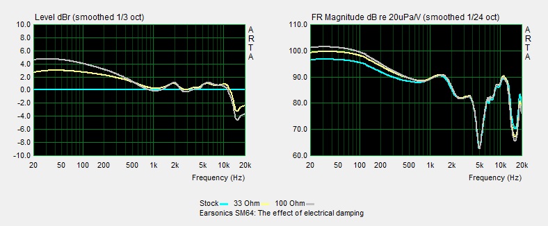
On the same page near the bottom of the series of graphs you find one about added resistors like for the cable you're asking about:
Both show the same measurements but presented differently. On the right is simply the FR with the various resistor values added, while the left uses the measure without extra resistor as reference for flat, so you only see the EQ curve from adding the resistors, and you should be able to notice how the more you add resistance in the cable, the more the EQ curve looks like the IEM's impedance curve(orange on the first image). And that's really what you need to take away. If the IEM has a high impedance at 3kHz and low impedance everywhere else, then adding resistance to the cable will lower the volume everywhere, but less so at 3KHz. Which is equivalent to EQing to boost 3kHz.
The graphs here are aligned to make the FR changes easier to notice, but of course the 100ohm case would be overall quieter than 33ohm itself quieter than no added resistor.
So can it be good to add resistors in your cable? The vast majority of the time the answer is no. But in a few cases, most people prefer the FR with extra resistance. One famous case would be the old etymotic ER4, where the ER4S was simply the ER4P with resistors in the cable. And because of it's specific impedance curve, the result would be boosted treble. Most users preferred the ER4S, but as I just said, that's a fairly rare counter example. For most IEMs, you'd rather avoid adding resistors. Even for the hiss discussed before with extra sensitive IEMs, it's probably better to change the DAP for a quieter one, or to use a voltage divider design instead of simply add resistors in series.
You might like to check
https://www.head-fi.org/threads/feedback-about-gears-stop-doing-it-wrong-impedance.866714/ where I rant about a very similar effect and people not knowing that it exists, but instead of a resistor in the cable, it's with amplifiers of different impedance values. As I said at the beginning, the IEM "sees"(I shouldn't write that...) cable+amp impedance, so it doesn't matter if the extra impedance come from the cable or the amp.
Just remember that with more impedance at the amp or cable, the EQ impact takes the shape of the IEM's impedance curve. It's stupidly over simplistic but not wrong. We could get our hands dirty and get into lots of details, plus there are other impacts about electrical damping(phase, some stuff in the low end, cases where the DAP has protection caps...), but I imagine the FR change from impedance is already plenty information and the one you're most likely to need for IEMs.
TLDR, outside particular cases and test purposes, such cables are not desirable.


") So I guess those cables have no use case with a very low ohm Shure SE846 and DAPs or DAC/AMPs with a low Headphone Output impedance, or the 7hz timeless that is a planar.
So I guess those cables have no use case with a very low ohm Shure SE846 and DAPs or DAC/AMPs with a low Headphone Output impedance, or the 7hz timeless that is a planar.
