Hi Rob,
I saw this post on another thread and it brought up something I hadn’t considered before. Is this a valid point, or how is it dealt with in your DAC designs?
https://www.head-fi.org/threads/hed...h-amt-technology.906270/page-54#post-15423215
thanks!
I assume you are referring to the PSU interaction point and not the one amplifier for the best transparency issue.
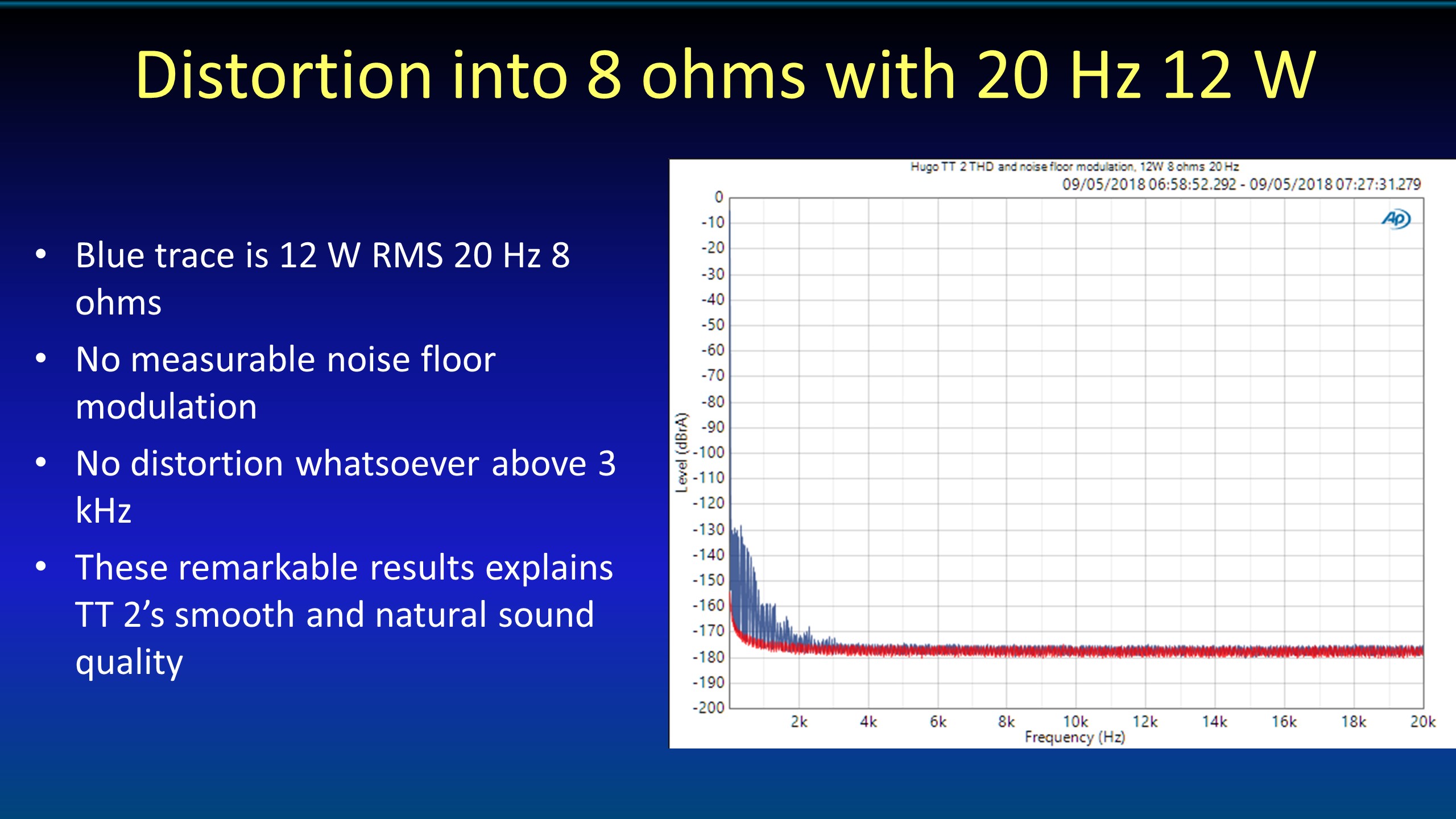
So output stages create distorted output currents, and these are very nasty, as they create infinite harmonics distortion. But this is an analogue problem, it's the same if it is a DAC or a linear power amplifier. To overcome it you have to be very careful - you need to isolate the noisy and distorted OP stage rails from the amp gain power rails, and to use an amp with very high power supply rejection ratio (PSRR). I do this naturally on all my DAC designs - and to prove that it's not an issue, then you look at the HF distortion using a 20 Hz high power output signal. If you get the OP stage PSU to be isolated from the gain stages and the DAC pulse array OP then you will see no HF distortion (assuming as well that the class AB output crossover distortion is also well handled). This is why the TT2 distortion plot is so unusual, as it proves that PSU distortion is eliminated as well as crossover distortion.
You can see the measurement here:
I don't think I have talked about the effects of distorted currents on the power rails at all as it's something I solved some 40 years ago! But it is a very significant issue.
So to make sure it's eliminated at the design stage, you take the worst case OP currents, take the worst case frequency (20 kHz), calculate the PSU impedance, then the error voltages, then the error voltage at the core PSU node, then the gain stage regulator line rejection ratio, then the gain stage PSRR, then you can calculate the error to make sure it's in the right ballpark. Then finally do a measurement like the TT2 one shown to confirm everything is OK, as although you can eliminate the issue at the design stage, you may get crosstalk effects such as ground return currents creating ground plane noise.
Hi Rob,
I have a delay question to offset all this noise talk!

Do you have a designed model for delay built into all of your DACs (differing with each product of course)? What I mean is that there are varying numbers of taps for each device but you use different FPGA chips to achieve that. Do your products manage to work through the tens or hundreds of thousands of taps in real time and even at the 768KHz maximum or do you build in an expected delay based on how fast the data can possibly get through the chip? I'm not suggesting delay is some kind of negative feature. I'm more curious about how well modern FPGA chips (that don't cost thousands of dollars) are able to pipeline this stuff through and at what cost. You must have to break the taps down into parallel blocks to make it fit in these little chips and they can only run so fast and at a necessary multiple of the audio data! The potential trade off sounds like an interesting topic.
I think I read the M-Scaler does have some delay because of the 1M+ taps with a separate mode to reduce the delay but how does this concept filter down through the lesser tapped products and even down to the Mojo? It's just a bit of fascinating side information that left me curious this evening.
Thanks!
Yes there is a direct relationship with a WTA filter, the tap length, and the oversampling ratio. That's fully defined as the filter performance - the actual implementation will make no difference to this delay. With the video mode on the M scaler, I replace the symmetrical filter with an asymmetric one; so the "future" path is shorter than "past" path. A shorter "future" path gives you a lower delay - as the future is created by adding a delay to the data, so that the filter sees into the future, which is something that is essential for a sinc type filter.
Hello Rob,
Does a usb to optical convertor which is powered by the computer (by usb) pose any issues such as transmitting RF noise from the computer into HMS and can the high quality clocks in these DDC'c add anything beneficial to a HMS/TT2 set up vs just using optical from a computer direct?
I think that's fine, except for the fact that you have extra circuitry and so more noise possibility. You won't get the intersecting loops as there is only one path back to the mains, and you can always run your lap-top off battery too. But if you run the lap-top off battery, and nothing else is connected to the lap-top, then USB is effectively perfect anyway, as no nett currents can flow into the DAC ground plane.
the matrix usb to optical convertor is supposed to contain a much higher quality femtosecond clock for timing and clocking the various sample rates used which is why i'm looking at it. whether this is beneficial with the HMS i don't know yet.
https://www.matrix-digi.com/en/products/314.html
I couldn't hear an improvement on the M scaler whilst listening to USB or optical with my office system which is mains powered - and with hideous amounts of gear attached too! Of course YMMV, but my experience is that the M scaler is pretty immune - so just keep it simple.


