USB Cables, Digital Signals, and YOU! Pt. 1
Nov 14, 2009 at 5:30 PM Thread Starter Post #1 of 37

oddity

100+ Head-Fier
Joined
Sep 28, 2009
Posts
132
Likes
11
This guide is intended to educate the reader on the Universal Serial Bus system and how it interacts with digital music.

We of the audiophile community are no strangers to cables. There are volumes of information available on the internet, as well as those funny analog mini-web pages called "books", on traditional analog audio cables and interconnects. But as we have moved forward in the digital age we continue to ignore the obvious; analog is on its way out. I don't know anyone who doesn't have an MP3 player or a computer. Conversely, I can count on one hand the number of people who carry around a CD player and regularly use a turn-table. Like it or not everything from LP's to CD's, and their dated interconnects, are becoming obsolete.

That being said, I have absolutely nothing against the folks who live by analog. I intend no offense.

Which brings me to my point; I believe that digital is the future of our hobby. And as of this writing the connection of choice is USB. There are faster connections available, but the availability of USB products shows that it is the connector of the future.

USB supports “plug’n’plug’play” with dynamically loadable and unloadable drivers. The user simply plugs the device into the bus. The host will detect this addition, interrogate the newly inserted device and load the appropriate driver all in the time it takes the hourglass to blink on your screen provided a driver is installed for your device. The end user needs not worry about terminations, terms such as IRQs and port addresses, or rebooting the computer. Once the user is finished, they can simply lug the cable out, the host will detect its absence and automatically unload the driver. Very convenient, but as we will see the USB itself has a few issues.


Don’t want to read this REALLY long post on USB Audio? Visit the links below:
Need computer audio help, go here: How to Get Audio into your Computer by TweakHeadz Lab
Want a no B.S. keeping it simple guide: Everything you wanted to know about USB 2.0 but were afraid to ask
Want a REALLY detailed USB guide, go here: USB in a NutShell - Chapter 1 - Introduction
Prefer to read a book instead: Jan Axelson's Lakeview Research

Table of Contents

1) A Quick Note: Bits n’ Bytes
2) Digital Audio Basics
3) Digital Reproduction: The Big Issue
4) EXTREMELY CONNECTED: USB vs. The Rest
5) USB Overview
6) USB Cable: A Deeper Look
7) Anatomy of a USB Cable
8) How USB works it’s Voodoo
9) USB Audio: From Signal to Song
10) The Really Technical Parts: Isochronous Transfers
11) This stuff makes my head hurt…
12) Getting the most out of your USB Port
Appendices:
Appendix I: Common USB Packet Fields
Appendix II: Transfer Details
Appendix III: USB Function Drivers – Audio
Appendix IV: Isochronous Transfer Variations
Appendix V: Commonly asked questions about jitter
Appendix VI: Advanced USB Specifications & Schematics
Appendix VII: Advanced USB & Digital Audio
Appendix VIII: Useful Links

Sources
 
Nov 14, 2009 at 6:09 PM Post #2 of 37
A Quick Note: Bits n’ Bytes

When you are dealing with digital audio, you are dealing with Bits.

By convention, bus and network speeds are denoted either in bit/s (bits per second) or byte/s (bytes per second). In general, parallel interfaces are quoted in byte/s and serial in bit/s. On devices like modems, bytes may be more than 8 bits long because they may be individually padded out with additional start and stop bits; the figures below will reflect this. Where channels use line codes (such as Ethernet, Serial ATA and PCI Express), quoted speeds are for the decoded signal.
Where two values are listed, the first value is the downstream rate and the second value is the upstream rate.
All quoted figures are in metric decimal units, where:
I.1 bit = Base Unit
II.1 byte = 8 bits
III.1 kbit = 1,000 bits
IV.1 Mbit = 1,000,000 bits
V.1 Gbit = 1,000,000,000 bits
VI.1 kB = 1,000 bytes
VII.1 MB = 1,000,000 bytes
VIII.1 GB = 1,000,000,000 bytes
IX.1 TB = 1,000,000,000,000 bytes


Digital Audio Basics

Audio signals created by digital synthesis originate entirely in the digital domain, in which case analog to digital conversion does not take place.

After being sampled with the ADC, the digital signal may then be altered in a process which is called digital signal processing where it may be filtered or have effects applied.

The digital audio signal may then be stored or transmitted. Digital audio storage can be on a CD, a digital audio player, a hard drive, USB flash drive, CompactFlash, or any other digital data storage device. Audio data compression techniques — such as MP3, Advanced Audio Coding, Ogg Vorbis, or FLAC — are commonly employed to reduce the file size. Digital audio can be streamed to other devices.

The last step for digital audio is to be converted back to an analog signal with a digital-to-analog converter (DAC). Like ADCs, DACs run at a specific sampling rate and bit resolution but through the processes of oversampling, upsampling, and downsampling, this sampling rate may not be the same as the initial sampling rate.

Sampling theorem

The Nyquist–Shannon sampling theorem states that perfect reconstruction of a signal is possible when the sampling frequency is greater than twice the maximum frequency of the signal being sampled,[4] or equivalently, when the Nyquist frequency (half the sample rate) exceeds the highest frequency of the signal being sampled. If lower sampling rates are used, the original signal's information may not be completely recoverable from the sampled signal.

For example, if a signal has an upper band limit of 100 Hz, a sampling frequency greater than 200 Hz will avoid aliasing and allow theoretically perfect reconstruction.

Oversampling

In some cases, it is desirable to have a sampling frequency more than twice the desired system bandwidth so that a digital filter can be used in exchange for a weaker analog anti-aliasing filter. This process is known as oversampling.

Undersampling

Conversely, one may sample below the Nyquist rate. For a baseband signal (one that has components from 0 to the Nyquist rate), this introduces aliasing, but for a passband signal (one that does not have low frequency components), there are no low frequency signals for the aliases of high frequency signals to collide with, and thus one can sample a high frequency (but narrow bandwidth) signal at a much lower sample rate than the Nyquist rate.

While the goal of both analogue and digital systems is to reproduce audio perfectly, there are several obstacles to achieving this, including:

Analog noise floor in the capturing circuitry has inherent capacitance and inductance that limits the bandwidth of the system, and resistance that limits the amplitude.

Analogue_Digital_Conversion.png


Digital quantization noise in the capturing circuitry, and sampling rate limits the bandwidth and its bit resolution limits the dynamic range (resolution of amplitude creation).

In order to achieve better fidelity, higher quality components are required.

A digital audio signal starts with an analog-to-digital converter (ADC) that converts an analog signal to a digital signal. The ADC runs at a sampling rate and converts at a known bit resolution. For example, CD audio has a sampling rate of 44.1 kHz (44,100 samples per second) and 16-bit resolution for each channel (stereo).

If the analog signal is not already band-limited then an anti-aliasing filter is necessary before conversion, to prevent aliasing in the digital signal. (Aliasing occurs when frequencies above the Nyquist frequency have not been band limited, and instead appear as audible artifacts in the lower frequencies).

SIDE BAR A
Frequencies and descriptions
Frequency (Hz) /Octave/Description
16 to 32/1st/The human threshold of feeling, and the lowest pedal notes of a pipe organ.
32 to 512/2nd to 5th/Rhythm frequencies, where the lower and upper bass notes lie.
512 to 2048/6th to 7th/Defines human speech intelligibility, gives a horn-like or tinny quality to sound.
2048 to 8192/8th to 9th/Gives presence to speech, where labial and fricative sounds lie.
8192 to 16384/10th/Brilliance, the sounds of bells and the ringing of cymbals. In speech, the sound of the letter "S" (8000-11000 Hz)


TI_DAC_TableB.gif


Digital Reproduction: The Big Issue
The Jitter Bug: Your Digital Enemy


Jitter is an often-debated subject on the web audiophile forums. Like cables, there tend to be believers and non-believers. The goal of this treatise is to educate and share the current state of my jitter understanding.

Most audiophiles do not even realize that they have jitter until it is reduced. I liken it to looking through a window made of really old glass, when glass had ripples and bubbles in it. There is a spreading and distortion that widens and defocuses some images and creates an overall mild distortion. It is still obvious what is on the other side of the window, but it is not coming through with crystal clarity. Reducing (you will notice that I do not say "removing") jitter is like replacing the glass with a clean, flat piece of glazing. Things are now visible in great detail and with a "vividness" that was not there with the rippling glass. Jitter can be blamed for much of the "fatigue" that results from listening to some digital playback systems, just like it is fatiguing peering through rippled glass for any length of time.

Some Annoying History


Jitter has been with us since the inception of the CD format by Sony and Philips in 1982. It is a pervasive problem with all digital audio. It has prevented digital audio, both CD's and computer-driven-audio from competing with good vinyl and tape for decades. It is only recently that manufacturers have become aware of the problem and developed improved chips and systems to deal with jitter.

What is Jitter?

Technically, playback jitter is the inaccuracy in the timing of the "ticks" of the clock that transfers the samples of digital data into the D/A converter chip. To move data in a digital system from one point to another, it is usually clocked. In order for the D/A conversion to work, a new data word must be presented to the D/A converter periodically, or at a fixed frequency. The system clock or clocks do this. In an ideal world, each transfer of data to the D/A on a clock tick should occur at a precise point in time. If some data transfers occur a tiny bit early and others occur a tiny bit late, this is jitter. It is kind of like a timepiece that ticks away the seconds, where the duration of each second is not exactly a second, but over a large number of seconds, the timepiece is still telling accurate time. The duration of some second intervals is slightly short and other intervals are slightly long, but the average of all of them still gives accurate time. Likewise, when digital audio is played-back, the clock "ticks" that present each new data word to the D/A converter can have shorter and longer intervals from one tick to the next. The effect of this jitter on the D/A conversion and the analog waveform is frequency modulation, the same type of modulation that is used for FM radio. The difference is that with FM radio, the carrier frequency is fixed and the jitter is the music signal that is modulating the frequency of the carrier wave. With digital audio, the carrier is the music and the jitter is the modulation. This makes it a much more complex signal than even FM radio. The jitter associated with digital streaming audio is usually a mix of non-correlated and correlated jitter, correlated being that jitter that is somehow related to the music data or waveform and uncorrelated usually being random jitter. Jitter has both an amplitude and a frequency component. We will later discuss which of these I believe is more important.

Difference between Audio Streaming and other data transfers

Digital audio streaming is a "real-time" process, meaning that the actual timing of the transfer of each data bit from the source to the D/A converter is important and must be as precise as possible. Data transfers to disk or a printer are not real-time because there is no urgency for the data to arrive at the printer or disk to prevent errors from happening. The data arrives whenever it does and then the device does its job with the data, either writing it to the disk or storing it in a print buffer. If the data does not arrive in time to be written on a particular sector of a disk, the hardware just waits for the disk to rotate again. Streaming audio data on the other hand must arrive at precise time intervals in order that the D/A device create an accurate representation of the original recording. If it does not "keep-up" the pace, then dropouts will occur and the D/A converter will fall out of sync. The clock that moves the data into the D/A cannot be missing any "ticks" and each tick must be precisely placed in time. The audio data transfer must include both 1) accurate data and 2) accurate timing, whereas non-real-time transfers only require accurate data.

Recording Jitter

The recording of digital data is essentially a periodic sampling of a voltage (the voltage being the music waveform created from an instrument or microphone), where the period in theory is very precise. These captured sample voltages are then converted to digital data words and stored in memory or on recording media. There is no timing information actually stored in the data samples, but the timing is implicit in the samples themselves. There is however control information, which specifies the sample-frequency that should be used for playback, and other info such as pre-emphasis and word-length. If the timing that captured these data samples included jitter, then this is a characteristic of the samples and cannot be realistically eliminated during playback. This recording jitter is always there in the music file. Playback jitter is another matter however.

Playback Jitter Contributions

Playback jitter originates from a large number of contributors, which are usually additive. These range from the master clock, which has its own jitter, to logic devices, to mechanical systems for spinning a CD. One digital cable can even add more jitter than another. Each contributor adds more jitter to the signal as it makes its way to the D/A converter. This summation of this jitter is the system jitter.

Here is a lengthy, but probably not complete list of jitter contributors, including how each of these can or might add jitter to a digital audio system:

1. Master Clock Jitter
This is the source clock for all of the data streaming timing, usually a quartz-crystal-controlled oscillator at a very high frequency. It may be a 11.2896MHz clock in a CD player for data sampled at 44.1kHz, or in computer audio systems, a clock that is software generated from an even higher frequency CPU clock. The jitter of these clocks is intrinsic to the crystal device, but also depends on the design of the oscillator circuit. In the case of the master clock being software generated, the jitter can also be dependent on the program code.

2. Servo-system/rotational jitter
This is the system in the CD player/Transport that determines the spin-rate of the CD. It is an electromechanical system. Even though most modern CD players have buffering of the data to create some tolerance to this jitter, there is usually a PLL (Phase-locked-loop) involved, which is usually still somewhat susceptible to jitter. For newer players that completely buffer the data at high-speed from a CDROM reader to a memory buffer, this jitter is not an issue.

3. Jitter from the pits on a CD
These are the pits in the CD media that represent the recorded data. Variation in the spacing of these pits result in jitter when reading the data. Commercially CD's created from a glass-master generally have more variation in the locations of the pits than a CD-R written at 1X speed on a good CD-R writer. Even though most modern CD players have buffering of the data to create some tolerance to this jitter, there is usually a PLL (Phase-locked-loop) involved, which is still somewhat susceptible to jitter. To determine if your player is susceptible, it is a simple experiment to re-write or "clone" a CD and then listen for playback differences from the commercial version. For newer players that completely buffer the data at high-speed from a CDROM reader to a memory buffer, this jitter is not an issue.

4. S/PDIF conversion
The S/PDIF interface was created by Sony/Philips to simplify the interconnect between digital audio devices. The deficiency in this interface is that it embeds the serial clock in the serial data-stream in order to achieve one-signal cabling. A superior interface would have included both a clock and a data signal, but we don't have this, so we live with S/PDIF. The S/PDIF interface must encode the data and clock into a single signal and then at the destination recover the clock(s) from the data-stream. The process of recovering the clocks can introduce new jitter since there is usually a PLL involved.

5. Logic buffering
The digital audio data must make its way through the system over wires/traces and sometimes through buffers, such as the buffer to drive the S/PDIF cable. Each of these buffers has finite reaction times and imprecise detection of changing signal levels. What this means is that even though the signal may not have much jitter coming into the buffer, it may exit with additional jitter. This jitter is a result of the speed of the device, thermal effects on the silicon die, power delivery on the die and even transmission-line effects.

6. Power subsystem
The DC power applied to each of the devices that must process or transmit the digital audio signal is critical. If this power varies in voltage, the devices will react differently to the applied digital signals. Power "noise" as it is referred to is probably one of the largest contributors to jitter. Voltage changes or "voltage droop" can happen anywhere on a circuit board, power cabling, or even on the silicon itself. Changes in power voltage will change the speed and reaction times of digital logic that is transmitting the digital signals resulting in jitter.

7. Toslink optical conversion
Optical conversion adds another layer of buffering on both the transmitting and receiving ends of the S/PDIF interface. This additional layer in itself adds jitter, regardless of whether it is optical or not because of (5). However due to its complexity, the optical interface adds more jitter than a simple logic buffer. For that reason, it has higher jitter/lower performance than a well-designed S/PDIF coax interface.

8. Digital Cables
Cables don't actively add jitter to the signal, however they can slow the signal transitions or "edges". When the edges are slowed, the receiver or buffer at the cable destination is less likely to detect the transition at the correct time with certainty, which results in jitter.

9. Transmission-line effects

TL effects are usually more of a problem on the S/PDIF coaxial cable, but may also be present on long traces on circuit boards. These occur because the signal transition is very fast and as a result, reflections occur on the wire or trace. The signal reflections from an earlier signal transition can return to the destination and "push" or displace a later signal edge, causing jitter. TL lines must be properly terminated and impedance-matched in order to minimize reflections and the potential resulting jitter. There are steps that can be taken to minimize this effect, such as using a longer S/PDIF cable. See:
spdif

10. Printed circuit board effects
There are at least two effects on a circuit board that can cause jitter, including signal crosstalk and ground-bounce. Crosstalk occurs when traces with high-speed signals are spaced closely. One signal induces voltage on the other signal. It is obvious how this can add to jitter. Ground-bounce occurs when the signal return current see a high-impedance on the circuit board due to ground-plane splits or long return paths. This creates a voltage drop in the ground-plane or return path. This voltage drop causes the signal to shift in voltage, which can result in jitter.
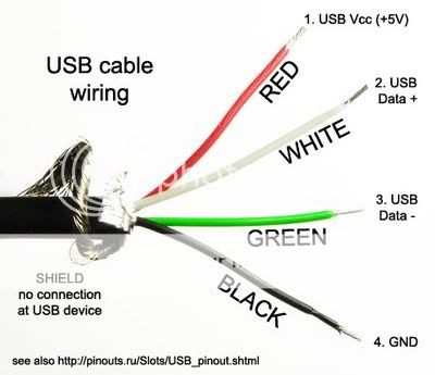
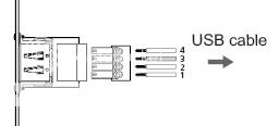
Jitter and USB
There is much misinformation on the forums about USB for audio streaming. USB is a fairly jittery interface on it's own. Some of the integrated circuit devices that were created to provide easy plug-and-play USB audio interfaces don't do enough to reduce USB jitter IMO. Many manufacturers adopted these plug-and-play devices to quickly and cheaply add USB to their DAC products. Unfortunately the less-than-stellar reviews that ensued had some of these manufacturers regretting these decisions. This gave USB a bad name in many circles.
Fortunately, there are other low-jitter USB interfaces available now that not only support 24/96, they even compete with the best CD playback devices. In 2009, I believe we will see USB support for 24/192 and even lower-jitter interfaces. USB is IMO the wired audio interface that will be most prevalent in the near future.

Jitter and Networked audio
Networked audio (Ethernet), both wired and WiFi is a unique case. Because the data is transmitted in packets with flow-control, re-try for errors and buffering at the end-point device, it is not as much of a real-time transfer as USB, S/PDIF or Firewire. The computer transmitting the data packets must still keep-up" the pace to prevent dropouts from occurring, but the real-time nature of the transfer is looser. Unlike with other protocols, there can be dead-times when no data is being transferred. Networking also avoids the use of the audio stack of the computer audio system since it treats all data essentially the same. This avoids kmixer on XP systems and the audio stacks on Mac and PC Vista. Because of the packet-transfer protocol of Ethernet and data buffering at the end-point, the jitter of the clock in the computer is a non-issue. The only clock that is important is the one in the end-point device. Examples of end-point devices are: Squeezebox, Duet and Sonos. This would seem to be the ideal situation, which it certainly is. The only problem that can occur is overloading the network with traffic or WiFi interference, which may cause occasional dropouts. The problem for audiophiles is that the majority of these end-point devices were designed with high-volume manufacturing and low-cost as requirements, with performance taking a lower priority. As a result, the jitter from these devices is higher than it could be. It should be the lowest of all the audio source devices available.

Jitter and Re-Clockers
There are a number of re-clockers available, some older and some newer technologies. There are three main types of re-clockers:
1) A true re-clocker that uses a free-running oscillator and stores data in a buffer
2) Re-clocker that uses a series of PLLs (Phase-Locked-Loops) to reduce jitter
3) Re-clocker that uses ASRC (Asynchronous Sample-Rate Conversion) to reduce jitter (also a PLL)
You will notice that I always use the terms: "reduce jitter" or "extremely low jitter", even with my own products. This is because it is impossible to completely eliminate jitter, contrary to the claims of some manufacturers.
The true re-clocker (1) can deliver the lowest jitter of the three types because it is not influenced by any outside signals.
A series of PLLs (2) will reduce jitter, but PLLs are affected by the jitter in the input signal to some extent. The more PLLs that are cascaded and the lower the filtering of the PLL loop filter, the better the jitter reduction will be. Some high-end DACs use this technique.
The ASRC up-sampler of (3) is somewhat sensitive to incoming jitter and has the disadvantage of changing the data by up-sampling it. If you don't like the sound of that particular hardware up-sampler, there is nothing you can do about it. Examples of this are in many modern DACs.
Re-clockers of the same type are not all equal either. The jitter of the master-clock in the re-clocker can vary. The design of the circuits, the power sub-system and circuit-board layout has a huge impact on the performance of a re-clocker. In order to achieve extremely low jitter levels, all of these disciplines must be mastered and the implementation must be flawless.
Low-jitter clock technology has improved dramatically in the last 2 years, so newer re-clockers will usually take advantage of this.

Jitter Correlation to Audibility
The correlation of jitter measurements to audibility is in its infancy IME. The problems start with the characterization of jitter. Generally, manufacturers of crystal oscillators specify jitter in terms of RMS jitter amplitude. The problem is that they often neglect to state that this is specified at 10kHz and higher. There is also no spectral or frequency content information specified. This makes it very difficult to tell which oscillators will have audible jitter or objectionable jitter.

For instance, Empirical Audio uses two oscillators that are both specified at 2psec RMS jitter. The two oscillators sound radically different to me when used in a re-clocker in a resolving audio system. This leads me to believe that the spectrum or frequency content of the jitter is as important or maybe even more important than the amplitude. I also believe that correlated jitter or jitter with a relationship to the data pattern or audio signal is also more audible than random jitter. This seems to be the consensus in a number of AES papers.
Studies by the AES (analysis, not human testing) conclude that these are the thresholds of audibility:

[1] 120psec P-P jitter audibility threshold for 16-bit DAC and 8psec P-P jitter audibility threshold for 20-bit DAC

[2] 20psec P-P of data-correlated jitter audibility threshold at certain frequencies and "A simple model of jitter error audibility has shown that white jitter noise of up to 180psec P-P can be tolerated in a DAC, but that even lower levels of sinusoidal jitter may be audible"
Since many measurements (that don't specify any particular frequency content) performed by Stereophile in

[3] are above 150psec or close to this, I do not believe that we have reached the limits of jitter audibility yet. I suspect that P-P jitter needs to be almost an order of magnitude smaller, or around 15psec to be inaudible in all systems.

The ability of the human ear/brain, particularly the trained ear, to hear minute differences, particularly data-correlated jitter, is grossly underestimated. The live listening AB/X studies published to date (that I have read) are inconclusive IMO. The systems used were not resolving enough IMO, the recording quality was not good enough and the test signals were random and not correlated and therefore inadequate to properly test for jitter audibility. I tend to believe the numbers arrived at by the AES analytical studies rather than the A/BX listening tests.

There are a series of double-blind tests being performed by many audiophiles using synthetic jitter tracks provided by HDTracks. These may shed some new light on true audibility. Again, the effectiveness of these experiments is only as good as the quality of the tracks provided, the jitter that was synthesized and the audio systems that are used for testing. The results from the first set of jitter tracks shows just how unresolving most audiophile systems are. There are couple that could pick out the majority of the tracks by increasing jitter, but the majority could not hear any difference between the tracks, even though the jitter ranged from 0 ns to 1000ns I believe.

Another interesting thing about audibility of jitter is its ability to mask other sibilance in a system. Sometimes, when the jitter is reduced in a system, other component sibilance is now obvious and even more objectionable than the original jitter was. Removing the jitter is the right thing to do however, and then replace the objectionable component. The end result will be much more enjoyable.
Jitter can even be euphonic in nature if it has the right frequency content. Some audiophiles like the effect of even-order harmonics in tubes, and like tubes, jitter distortion can in some systems "smooth" vocals. Again, the right thing to do is reduce the jitter and replace the objectionable components. It is fairly easy to become convinced that reducing jitter is not necessarily a positive step, however this is definitely going down the garden path and will ultimately limit your achievement of audio nirvana.

Sibilance in a system caused by preamp, amps and other components and cables can also be so high that changes in jitter are not very audible. This is why there is such contention on the web forums about jitter and its importance. What matters in the end is if you are happy with the sound of your system, and whether or not you can hear this distortion.

For Jitter FAQ, Please see Appendix V
 
Nov 14, 2009 at 6:18 PM Post #3 of 37
EXTREMELY CONNECTED: USB vs. The Rest

Anatomy of a typical cable
It is important to understand what makes up a typical cable. There are five main parts of a cable that affect signal quality:

Wire-cutaway.gif


The outer jacket contains the inner materials and protects the cable from damage.

The shielding material filters out any radio frequency interference (RFI) and electromagnetic interference (EMI) that's attracted to the conductor and which can cause unwanted noise. It's frequently composed of more than one layer, like the braid and foil layers pictured above.

The dielectric is an insulating material between the conductor and the shielding material that helps protect the signal.
The conductor is the part of the cable through which the signal actually passes.

And finally, the connector is the part of the cable that actually plugs into your gear. The type of connector varies depending on the type and quality of your components.

Common Cables

Audio interconnects

Good-quality cables can mean the difference between full, engaging sound, and audio that's missing frequencies on the high or low end, sounding fuzzy or flat. When shopping for better audio cables, it's a good idea to look for:

Cables that use an oxygen-free copper (OFC) center conductor — it's more likely to pass signals accurately, with minimal signal loss.
The best shielding you can afford to combat interference. Cables that include two separate shields — one made of braided copper, to guard against RFI, and one made of foil, to guard against EMI — help assure that no annoying buzzes or pops are introduced into the signal.

Good connectors that provide constant, high-pressure contact with your components' jacks. If the cable you're considering uses metal connectors, look for gold-plating to prevent corrosion and get a reliable, high-quality signal transfer.

Before we move on to explore the world of USB, we should first look at it’s predecessors’, as well as some of it’s possible successors.

Here is a breakdown of the major types of cables you encounter in audio and video:

tb_04-1.jpg


SERIAL: Serial cables transfer data one bit at a time. Mainly found on PCs and commonly used to connect a monitor and external modem, these connectors were originally used to link computers together to transfer large files.

tb_05-1.jpg


ETHERNET: The Ethernet connector is specifically used for high-speed Internet connections and for all kinds of networking. It plugs into the Ethernet port on a computer and leads to a cable or DSL modem. It also can plug into a network hub (a box that connects lots of cables together).

tb_06.jpg


PHONE JACK: The telephone jack is a no-brainer, and yes, it still connects your phone to the wall. For computer purposes, it remains the way millions of Americans connect to the Internet.

svideo.jpg


S-VIDEO: S-Video (or Super-Video) cable carries video brightness and color signals separately and is known to provide a clean, sharp image. This connector is used for devices such as portable DVD players and camcorders.

l703HDMIX2M-o_new.jpg


HDMI: HDMI (High-Definition Multimedia Interface) delivers crystal-clear digital audio and video via a single cable. It uses a 19-pin connector to transfer audio and video signals in the digital language of 1s and 0s between components, eliminating the compromised sound quality caused by digital-to-analog conversions and reconversions. This surround-sound-capable cable is the only one that supports up to 8 channels of super-high-quality "lossless" soundtracks, including all the latest high-resolution audio formats from Blu-ray, like Dolby® TrueHD and DTS® HD-Master Audio.

m703OPTA1M-f.jpg


Optical
: Optical cables transmit digital audio signals as pulses of light. Like coaxial (below), it's also surround-sound-capable, but can only deliver 5.1-channels of audio and can't carry the new high-resolution formats from Blu-ray. The sound quality of optical and coaxial cables is about the same, though optical connections are more common these days.

m119DC4002M-f.jpg


Coaxial: What it does: Coaxial digital cables look on the surface like standard analog RCA cables; however, you should avoid using a standard audio interconnect to transfer a coaxial digital signal. Cables engineered specifically to pass a digital signal provide roughly 75-ohm impedance and wider frequency bandwidth, ensuring superior signal transfer. Like optical (above), it's also surround-sound-capable, but can only deliver 5.1-channels of DVD-quality audio. You'll get about the same sound quality from coaxial and optical.

l703DB1MX-f_MT.jpg


XLR: XLR is a connection primarily used with professional audio gear that requires "balanced" audio. The connector has three pins — one for the positive conductor, one for the negative conductor, and one for the ground wire or shield. When an amplifier receives the signals from an XLR cable, it's able to compare the signal coming from each conductor and reject any differences that it detects, which indicate noise. XLR is thus less susceptible to external noise sources and better for applications that require exceptional sound quality over long runs. XLR connections are mainly used for analog audio, but there are also digital XLR cables available.

l119i4SACD2.jpg


Multi-channel analog audio: What it does: Multi-channel analog audio cables use six to eight stereo RCA cables to transfer five to seven full channels and one low-frequency channel of audio.

l043181422.jpg


Two-channel analog audio: What it does: The most basic audio connection, two-channel analog audio cables use two stereo RCA cables bound together to transfer two channels of audio. You probably recognize the standard white and red RCA plugs — this is the type of cable most commonly found in the box with audio components.

l119XGL400.jpg


Gaming Console Connections: Recommend for use with gaming consoles that are HDMI capable.

m158VMC30MH-f.jpg


Mini-HDMI: A smaller version of the common HDMI cable. Rarely used in audio, found mostly on HD capable portable electronics.
 
Nov 14, 2009 at 6:30 PM Post #4 of 37
USB Overview

Universal Serial Bus (USB) is a hardware interface for low-speed peripherals such as keyboards, joysticks, scanners, printers, telephony devices, and MPEG-1 and MPEG-2 digital video. The electrical design of USB limits the maximum cable length to 5 meters for full-speed devices and up to 3 meters for low-speed devices. Up to 5 hubs can be connected in series to allow for an extended cable run. Up to 127 devices (theoretical limit) can be attached to a single host computer. The hot-swap capability allows a USB device to be plugged in or unplugged without turning the system off. USB devices may be plugged into a USB receptacle on the PC, into a multi-port USB hub or into a USB device that also functions as a hub for other devices.
The Universal Serial Bus

So here is everything you ever wanted to know about the humble USB system, which is probably way more than you need to know.

USB is a peripheral bus specification developed by PC and tecom industry leaders -- Compaq, DEC, IBM, Intel, Microsoft, NEC and Northern Telecom -- that brings plug and play of computer peripherals outside the box, eliminating the need to install cards into dedicated computer slots and reconfigure the system. Personal computers equipped with USB allow computer peripherals to be automatically configured as soon as they are physically attached - without the need to reboot or run setup. USB also allows multiple
devices -- up to 127 -- to run simultaneously on a computer, with peripherals such as monitors and keyboards acting as additional plug-in sites, or hubs.

USB was developed by a group of seven companies that saw a need for an interconnect to enable the growth of the blossoming Computer Telephony Integration Industry. The seven promoters of the USB definition are; Compaq, Digital Equipment Corp, IBM PC Co., Intel, Microsoft, NEC and Northern Telecom.

A Brief History of USB

The first Universal Serial Bus (USB) cable was released to the public in 1996 as a way to create a simple, universal way to connect external devices to the personal computer. Since its inception, the USB format has gone through several iterations of upgrades:
USB 1.0: A low speed rate of 1.5 Mbit/s is defined by USB 1.0. It is very similar to "full speed" operation except each bit takes 8 times as long to transmit. It is intended primarily to save cost in low-bandwidth human interface devices (HID) such as keyboards, mice, and joysticks.

USB 1.1: The full speed rate of 12 Mbit/s is the basic USB data rate defined by USB 1.1. All USB hubs support full speed.

USB 2.0: A hi-speed (USB 2.0) rate of 480 Mbit/s was introduced in 2001. All hi-speed devices are capable of falling back to full-speed operation if necessary; they are backward compatible. Connectors are identical.

The Future of USB

USB 3.0: A SuperSpeed (USB 3.0) rate of 5.0 Gbit/s. The USB 3.0 specification was released by Intel and partners in August 2008, according to early reports from CNET news. The first USB 3 controller chips were sampled by NEC May 2009 and products using the 3.0 specification are expected to arrive beginning in Q3 2009 and 2010.USB 3.0 connectors are generally backwards compatible, but include new wiring and full duplex operation. There is some incompatibility with older connectors.

Standard Devices: USB Classes

In order to simplify the connection of USB Devices, the USB community have defined a number of standard protocols (called Classes) that host software can support in a uniform manner.

Class name

Human Interface Device (HID)
Mass Storage
Communication
Printer
Audio
Still Image
Media Transfer
Bluetooth HCI
USB Wireless Adapter
Video
Hub
Wireless Controller
Smart Card
Test & Measurement

Pieces of USB

The three main components of a USB system are the USB Host, hubs and devices. Devices are the endpoints of the system and include hardware such as printers, mice, keyboards and storage devices. Devices are the farthest downstream on the bus. Multiple USB devices can connect to a single port on the host computer through a hub. The root hub is the central hub that connects USB functions in the host to the devices. The host is the central connection point in a USB system. In most cases, this is integrated with the motherboard of a PC. Some level of software support is required in the host device. This is often specific to the operating system used and most operating systems have USB support integrated into them. Support is built into versions of Windows and can be added as modules in Linux when the kernel is built. Irix operating systems currently do not support USB.
The bus interconnect includes the physical medium, cables, topology and protocol layers needed to form the connections in a USB system. The cables consist of two powered lines for supplying power to bus-powered devices and two wires for sending and receiving data. The topology is a tiered-star model with the host computer at the top and a hub device centered at each device star. The host must have a direct data path to each device.

The USB: Identification and Explanation


tb_001.jpg


USB 1.1: Introduced in 1997, USB 1.1 is a high-speed digital connector used to hook all kinds of devices to your computer at 12 megabits per second (Mbps). If you're not happy with the two 1/2-in. USB 1.1 ports included on your computer, get a USB hub, which will let you attach up to 127 devices.

tb_02-1.jpg


USB 2.0: This updated version of USB 1.1 was first seen in 2003. It transfers data at a whopping 480 Mbps. But not to worry, USB 2.0 is backward compatible and will work with your older USB devices (though at only 12 Mbps).

tb_03-1.jpg


FIREWIRE: Although FireWire has only a 400-Mbps interface, compared to USB 2.0's 480 Mbps, in real-world usage it is faster

Typical USB Connections

USB ports have a Type A socket. All USB cables permanently attached to a device have a Type A plug. Devices that use a separate USB cable have a square Type B socket. USB cables have one Type A and one Type B plug. Some devices such as digital cameras may use small proprietary plugs and sockets replacing the Type B plug and socket.

USBconnectiondiagram.jpg


USB General FYI

The Universal Serial Bus has the following features:
-The computer acts as the host.
-Up to 127 devices can connect to the host, either directly or by way of USB hubs.
-Individual USB cables can run as long as 5 meters; with hubs, devices can be up to 30 meters (six cables' worth) away from the host.
-With USB 2., the bus has a maximum data rate of 480 megabits per second.
-A USB cable has two wires for power (+5 volts and ground) and a twisted pair of wires to carry the data.
-On the power wires, the computer can supply up to 500 milliamps of power at 5 volts.
-Low-power devices (such as mice) can draw their power directly from the bus. High-power devices (such as printers) have their own power supplies and draw minimal power from the bus. Hubs can have their own power supplies to provide power to devices connected to the hub.
-USB devices are hot-swappable, meaning you can plug them into the bus and unplug them any time.
-Many USB devices can be put to sleep by the host computer when the computer enters a power-saving mode.
- Some piece of software busily running in the background cannot "slow down" the bus.

Myths about USB

-The host (computer) is in complete control of the bus, there is no way too many devices trying to talk at once can "overload" the bus such as can happen on an Ethernet.

-The USB bus works very differently than an Ethernet connection works.

-Data is sent out in frames that go out every millisecond. This happens whether there is any data in them or not. The rate at which the frames go out is determined by the host transmitter, not by the speed at which the computer is running, or the software running on it.
 
Nov 14, 2009 at 6:35 PM Post #5 of 37
USB Cable: A Deeper Look

Here are a few of the standard technical specifications for the common USB Cable:

Data Transfer

The Full-speed USB 1.1 maximum bandwidth of 12 Mbits/sec is equivalent to a data transfer speed of 1.5 Mbytes/sec with Hi-speed USB 2.0 dramatically increasing this to 480 Mbits/sec. A Low-speed rate of 1.5Mbits/sec is used for HI (Human Input Devices) such as keyboards, joysticks etc. control, Interrupt, Bulk and Isochronous transfer modes are supported. A USB device indicates its speed by pulling either the D+ or D- line high to 3.3 volts. The pull-up resistors at the device end are also used by the host or hub to detect the presence of a device connected to the port.

Data signals are transmitted on a twisted pair labeled D+ and D− collectively using half-duplex differential signaling to combat the effects of electromagnetic noise on longer lines. D+ and D− usually operate together; they are not separate simplex connections. Transmitted signal levels are 0.0-0.3 volts for low and 2.8-3.6 volts for high. A NRZI (Non Return to Zero Invert) encoding scheme used to send data with a sync field to synchronize the host and receiver clocks.

Data Signaling Rate

High speed data is clocked at 480.00Mb/s with a data signaling tolerance of ± 500ppm.

Full speed data is clocked at 12.000Mb/s with a data signaling tolerance of ±0.25% or 2,500ppm.

Low speed data is clocked at 1.50Mb/s with a data signaling tolerance of ±1.5% or 15,000ppm.
(USB clocking information)

USB power usage

The USB bus supplies 5V DC regulated power (maximum 500mA)through each port on pins 1 and 4 (pins 1 & 5 on mini-USB). These pins are longer than the data pins to ensure that the power connections mate first and un-mate last. Low-power devices that might normally require a separate AC adapter can therefore be powered via the USB cable, eliminating the need for associated AC adaptors. Bus-powered hubs derive all their power from the USB bus. Powered-hubs are powered from their own AC adapter and provide better power distribution to downstream devices. Port-switching USB hubs isolate all ports from each other so that a faulty device will not cause all other the devices on the same bus to also fail. The specification provides for no more

USB Power


Bus-powered hubs: Draw Max 100 mA at power up and 500 mA normally.

Self-powered hubs: Draw Max 100 mA, must supply 500 mA to each port.
Low power, bus-powered functions: Draw Max 100 mA.

High power, bus-powered functions: Self-powered hubs: Draw Max 100 mA, must supply 500 mA to each port.

Self-powered functions: Draw Max 100 mA.

Suspended device: Max 0.5 mA

USB voltage

Supplied voltage by a host or a powered hub ports is between 4.75 V and 5.25 V. Maximum voltage drop for bus-powered hubs is 0.35 V from its host or hub to the hubs output port. All hubs and functions must be able to send configuration data at 4.4 V, but only low-power functions need to be working at this voltage. Normal operational voltage for functions is minimum 4.75 V.

The twisted pair data wires and the drain wire are 28AWG with the non-twisted power wires being from 28AWG to 20AWG. A USB cable with 20AWG power conductors will give a maximum usable length of 5 meters.
Cables have only plugs, and hosts and devices have only receptacles.


USB cable shielding

Shield should only be connected to Ground at the host. No device should connect Shield to Ground. Maximum length of cable is about 5 m for AWG20 and 0.8 m for AWG28 cable. Standard USB Plugs and Receptacles

The plugs and receptacles have 4-contacts and are rectangular in shape with the contact opening of a Type A plug or receptacle measuring approximately 13.1(W) x 5.5(H) mm. The contact opening on standard Type B USB plugs and receptacles measures approximately 5.6(W) x 3.2(H)mm.

Shielded:
Data: 28 AWG twisted
Power: 28 AWG - 20 AWG non-twisted

Non-shielded:
Data: 28 AWG non-twisted
Power: 28 AWG - 20 AWG non-twisted
 
Nov 14, 2009 at 6:47 PM Post #6 of 37
Anatomy of a USB Cable

Standard Wire Technical Data

USB signals are transmitted on a braided pair data cable with 90Ω ±15% Characteristic impedance, labeled D+ and D−. Prior to USB 3.0, These collectively use half-duplex differential signaling to reduce the effects of electromagnetic noise on longer lines. Transmitted signal levels are 0.0–0.3 volts for low and 2.8–3.6 volts for high in full speed (FS) and low speed (LS) modes, and −10–10 mV for low and 360–440 mV for high in hi-speed (HS) mode.

In FS mode the cable wires are not terminated, but the HS mode has termination of 45 Ω to ground, or 90 Ω differential to match the data cable impedance, reducing interference of particular kinds. USB 3.0 introduces two additional pairs of shielded twisted wire and new, mostly interoperable contacts in USB 3.0 cables, for them. They permit the higher data rate, and full duplex operation.


Wiring System

The USB cable is both very simple and very powerful. It is able to simultaneously transmit and receive data, and supply power to a device at the same time. Below is a breakdown of how a USB cable is wired.

4001_02.gif


The maximum length of a standard USB cable (for USB 2.0 or earlier) is 5.0 meters (16.4 ft). The primary reason for this limit is the maximum allowed round-trip delay of about 1,500 ns. If USB host commands are unanswered by the USB device within the allowed time, the host considers the command lost. When adding USB device response time, delays from the maximum number of hubs added to the delays from connecting cables, the maximum acceptable delay per cable amounts to be 26 ns.

The USB 2.0 specification requires cable delay to be less than 5.2 ns per meter (192,000 km/s, which is close to the maximum achievable speed for standard copper cable). This allows for a 5 meter cable. The USB 3.0 standard does not directly specify a maximum cable length, requiring only that all cables meet an electrical specification. For copper wire cabling, some calculations have suggested a maximum length of perhaps 3m. No fiber optic cable designs are known to be under development, but they would be likely to have a much longer maximum allowable length, and more complex construction.

Twisted Information: The USB Data Cable pairing

The data cables for USB 1.x and USB 2.x use a twisted pair to reduce noise and crosstalk. They are arranged much as in the diagram below. USB 3.0 cables are more complex and employ shielding for some of the added data lines (2 pairs); a shield is added around the pair sketched

400px-USB_Twisted_Pairsvg.png


Inside the USB Cable: The Whole Story

USB-cable-wiring.jpg


This table describes the basic USB Cable Color Scheme, and serves as a reference for the pictures below it.

Pin No./ Signal/Cable Color
1/+ VCC/ Red
2/Data - /White
3/Data + /Green
4/GND/Black


The Connectors

Here is a diagram of the standard USB pin-out.

180px-USBsvg.png


The common USB wire technical specifications are listed in the table below.

USB-Cord-Drawing.gif


Pin/Signal/Description/

1/USB Vcc (Vbus)/usually RED, wire should be 20-28 AWG
2/USB Data -/usually WHITE, wire should be 28 AWG
3/USB Data +/usually GREEN, wire should be 28 AWG
4/GND/usually BLACK, wire should be 20-28 AWG


Standard USB Pin-out & Cable Color Code
PinWire ColorFunction
1RedV BUS (+5V)
2WhiteD-
3GreenD+
4BlackGround

Mini-USB Type-A Pin-out & Cable Color Code
PinWire ColorFunction
1RedV BUS (+5V)
2WhiteD-
3GreenD+
4Joined to pin 5 ID
5BlackGround

Mini-USB Type-B Pin-out & Cable Color Code
PinWire ColorFunction
1RedV BUS (+5V)
2WhiteD-
3GreenD+
4Not connected (*)ID
5BlackGround
(*) Sometimes joined to pin 5 via a resistor

Plug & Receptacle Pin-outs:

Even though the original idea behind the USB system was to create a “universal” way of connecting devices to the home computer, there have been a number of changes and variations to the standard serial bus. Below are some examples of those variations.

PlugsReceptacles
Series A
Series B
Mini-USB Series A
Mini-USB
Series B


271px-Types-usb_newsvg.png


Mini-USB Plugs and Receptacles

USB-Dimensions.gif


Mini-USB plugs, receptacles and cables were primarily introduced for USB OTG (Universal Serial Bus On The Go) devices such as mobile phones, PDAs, digital cameras etc. The USB OTG specification allows a single port to act as either a host or a device - chosen by which end of the cable plugs into the socket on the unit. After the cable is connected and the units are synchronized, the units may even swap ends under program control. This ability targets units such as PDAs where the USB link might connect to a PC's host port with the PDA as a device or alternatively connect the PDA as a host to a keyboard.

Two small form factor plugs have been defined (Mini-A and Mini-B) along with a universal receptacle (Mini-AB) that accepts either a Mini-A plug or a Mini-B plug. . Mini-A, Mini-B, and Mini-AB connectors are identified easily by color. The specification nominates that the insulator plastic inside Mini-A plugs and receptacles is always white. In Mini-B connectors it's always black, and in Mini-AB receptacles it's always colored grey. The plugs and receptacles have 5 contacts with contacts 4 & 5 joined together inside the Mini-A plug. Mini-USB plugs and receptacles are rectangular in shape, with the contact opening measuring approximately 6.8(W) x 3.1(H) mm.

Pin/Name/Cable color/Description
1/VCC/Red/+5 VDC
2/D-/White/Data -
3/D+/Green/Data +
X/ID/ May be N/C, GND or used as an attached device presence indicator (shorted to GND with resistor)
4/GND/ Black/ Ground
 
Nov 14, 2009 at 6:58 PM Post #7 of 37
How USB works it’s Voodoo


In/Out Protocol

The Southbridge, also known as an I/O Controller Hub (ICH) or a Platform Controller Hub (PCH) in Intel systems (AMD, VIA, SiS and others usually use 'Southbridge'), is a chip that implements the "slower" capabilities of the motherboard in a Northbridge/Southbridge chipset computer architecture.

The Northbridge, also known as a memory controller hub (MCH) or an integrated memory controller (IMC) in Intel systems (AMD, VIA, SiS and others usually use 'Northbridge'), is one of the two chips in the core logic chipset on a PC motherboard, the other being the Southbridge.

The Southbridge can usually be distinguished from the Northbridge by not being directly connected to the CPU. Rather, the Northbridge ties the south bridge to the CPU. Through the use of controller integrated channel circuitry, the Northbridge can directly link signals from the I/O units to the CPU for data control and access

How USB Talks and Listens

USB ‘talks’ to other devices and ‘listens’ to them at the same time, it can even ‘feed’ them power. Below is a description of how this happens.

USB communication takes the form of packets. Initially, all packets are sent from the host, via the root hub and possibly more hubs, to devices. Some of those packets direct a device to send some packets in reply.

Packets are made of 8-bit bytes, transmitted least-significant bit first. The first byte is a packet identifier (PID) byte. The PID is actually 4 bits; the byte consists of the 4-bit PID followed by its bitwise complement. This redundancy helps detect errors.

Each USB transaction consists of a Packet, with the host initiating all transactions:

Token Packet (Header defining what it expects to follow)
Optional Data Packet, (Containing the payload)
Status Packet (Used to acknowledge transactions and to provide a means of error correction)


Start of Frame Packets

The SOF packet consisting of an 11-bit frame number is sent by the host every 1ms ± 500ns on a full speed bus or every 125 µs ± 0.0625 µs on a high speed bus.

SyncPID/Frame Number/CRC5/EOP

Most functions will have a series of buffers, typically 8 bytes long. Each buffer will belong to an endpoint - EP0 IN, EP0 OUT etc. Say for example, the host sends a device descriptor request. The function hardware will read the setup packet and determine from the address field whether the packet is for itself, and if so will copy the payload of the following data packet to the appropriate endpoint buffer dictated by the value in the endpoint field of the setup token. It will then send a handshake packet to acknowledge the reception of the byte and generate an internal interrupt within the semiconductor/micro-controller for the appropriate endpoint signifying it has received a packet. This is typically all done in hardware.
The software now gets an interrupt, and should read the contents of the endpoint buffer and parse the device descriptor request.

Endpoints

Endpoints can be described as sources or sinks of data. As the bus is host centric, endpoints occur at the end of the communications channel at the USB function. At the software layer, your device driver may send a packet to your devices EP1 for example. As the data is flowing out from the host, it will end up in the EP1 OUT buffer. Your firmware will then at its leisure read this data. If it wants to return data, the function cannot simply write to the bus as the bus is controlled by the host. Therefore it writes data to EP1 IN which sits in the buffer until such time when the host sends a IN packet to that endpoint requesting the data. Endpoints can also be seen as the interface between the hardware of the function device and the firmware running on the function device.

All devices must support endpoint zero. This is the endpoint which receives all of the devices control and status requests during enumeration and throughout the duration while the device is operational on the bus.

Pipes

While the device sends and receives data on a series of endpoints, the client software transfers data through pipes. A pipe is a logical connection between the host and endpoint(s). Pipes will also have a set of parameters associated with them such as how much bandwidth is allocated to it, what transfer type (Control, Bulk, Iso or Interrupt) it uses, a direction of data flow and maximum packet/buffer sizes. For example the default pipe is a bi-directional pipe made up of endpoint zero in and endpoint zero out with a control transfer type.

200px-USB_pipes_and_endpoints_ensvg.png


USB defines two types of pipes:

Stream Pipes have no defined USB format, that is you can send any type of data down a stream pipe and can retrieve the data out the other end. Data flows sequentially and has a pre-defined direction, either in or out. Stream pipes will support bulk, isochronous and interrupt transfer types. Stream pipes can either be controlled by the host or device.

Message Pipes have a defined USB format. They are host controlled, which are initiated by a request sent from the host. Data is then transferred in the desired direction, dictated by the request. Therefore message pipes allow data to flow in both directions but will only support control transfers.


For a highly detailed description of how packets really work, please see Appendix I

USB has four types of communication transfer modes: Control, Interrupt, Bulk, and Isochronous.

-Control mode is initiated by the host. In this mode, every data transfer must send data in both directions, but only in one direction at a time. The control mode is used mainly for initialization of devices, but it can also be used to transfer small amounts of data.

-In interrupt mode, interrupts do not occur in the usual sense. As in control mode, the host has to initiate the transfer of data. Interrupt mode works by the host querying devices to see if they need to be serviced.

-Bulk mode and isochronous mode complement each other in a sense. Bulk mode is used when data accuracy is of prime importance, but the rate of data transfer is not guaranteed. An example of this would be disk drive storage.

-Isochronous mode sacrifices data accuracy in favor of guaranteed timing of data delivery. An example of this would be USB audio speakers.

You can have one or more of these data transfer formats identified in your device. Control mode is needed as a minimum for all USB devices for the query and setup of your device with Windows. If any of the following modes are required, Control mode also needs to be included.

If data accuracy is important, you will need to use bulk mode, but you will need to give up guaranteed timing of data delivery as USB tends to give bulk mode its lowest priority. Bulk mode transfer is only available in high speed mode and includes error checking.

If guaranteed timing of data delivery is more important than data accuracy, then you need to use isochronous mode of transfer. Isochronous mode transfer is also only available in high speed mode. You need to sacrifice one primary need for the other in these cases, i.e., transfer rate verses accuracy.

Fast Talker: Transfer Mode Specifics


USB has four different ‘accents’ when it ‘speaks’. The information below details how fast each ‘accent’ can ‘talk’.


Maximum Theoretical transfer rates(all Kbytes/sec)
Transfer Type/Low-speed/Full-Speed/ High-speed/
Control/24/832/15,872/
Interrupt/0.8/64/24,576/
Bulk/-/1,216/53,248/
Isochronous/-/1,023/24,576/

The Basics of the Four:


The USB specification provides for the following data transfer types:

Control - used by the Host to send commands or query parameters. Packet lengths are 8 bytes for Low speed, 8-64 for Full and 64 for High Speed devices.

-Control Transfer is mainly intended to support configuration, command and status operations between the software on the host -and the device.
-This transfer type is used for low-, full- and high-speed devices.
-Each USB device has at least one control pipe (default pipe), which provides access to the configuration, status and control information.
-Control transfer is bursting, non-periodic communication.
-The control pipe is bi-directional - i.e. data can flow in both directions.
-Control transfer has a robust error detection, recovery and retransmission mechanism and retries are made without the involvement of the driver.
-The maximum packet size for control endpoints can be only 8 bytes for low-speed devices; 8, 16, 32, or 64 bytes for full-speed devices; and only 64 bytes for high-speed devices.


Interrupt - badly named it is in fact a polled message from the Host which has to request specific data of the Device. Used by Devices which will be sending small amounts of data (e.g. mice or keyboards).

-Interrupt Transfer is intended for devices that send and receive small amounts of data infrequently or in an asynchronous time frame.
-This transfer type can be used for low-, full- and high-speed devices.
Interrupt transfer type guarantees a maximum service period and that delivery will be re-attempted in the next period if there is an error on the bus.
-The interrupt pipe, like the isochronous pipe, is unidirectional and periodical.
-The maximum packet size for interrupt endpoints can be 8 bytes or less for low-speed devices; 64 bytes or less for full-speed devices; and 1,024 bytes or less for high-speed devices.


Bulk - Used by Devices that send or receive data in quantity such as a printer. Variable length blocks of data are sent or requested by the Host (max length is 64-byte- full speed, 512 -high speed), are verified with a CRC and their receipt is acknowledged. This mechanism is not used by time critical peripherals as it takes whatever bandwidth is left by the other mechanisms.

-Bulk Transfer is typically used for devices that transfer large amounts of non-time sensitive data, and that can use any available bandwidth, such as printers and scanners.
-This transfer type can be used by full-speed and high-speed devices, but not by low-speed devices.
-Bulk transfer is non-periodic, large packet, bursting communication.
-Bulk transfer allows access to the bus on an "as-available" basis, guarantees the data transfer but not the latency, and provides an error check mechanism with retries attempts. If part of the USB bandwidth is not being used for other transfers, the system will use it for bulk transfer.
-Like the other stream pipes (isochronous and interrupt), the bulk pipe is also unidirectional, so bi-directional transfers require two endpoints.
-The maximum packet size for bulk endpoints can be 8, 16, 32, or 64 bytes for full-speed devices, and 512 bytes for high-speed devices.


Isochronous - Used for devices that stream data in real time without any error recovery such as audio channels. For them losing some data occasionally is better than the glitch resulting from a re-transmit. Packet sizes can be up to 1024 bytes.

-Isochronous Transfer is most commonly used for time-dependent information, such as multimedia streams and telephony.
-This transfer type can be used by full-speed and high-speed devices, but not by low-speed devices.
-Isochronous transfer is periodic and continuous.
-The isochronous pipe is unidirectional, i.e. a certain endpoint can either transmit or receive information.
-Bi-directional isochronous communication requires two isochronous pipes, one in each direction.
-USB guarantees the isochronous transfer access to the USB bandwidth (i.e. it reserves the required amount of bytes of the USB frame) with bounded latency, and guarantees the data transfer rate through the pipe, unless there is less data transmitted.
-Since timeliness is more important than correctness in this type of transfer, no retries are made in case of error in the data transfer. However, the data receiver can determine that an error occurred on the bus.

Want to know more about Transfer modes? See Appendix II for details.
 
Nov 14, 2009 at 7:02 PM Post #8 of 37
USB Audio: From Signal to Sound


How USB packages and sends an audio signal:

There is a fundamental difference between the transfer of computer data and digital audio signals. Computers are able to transfer digital data without loss, because the data moves in the robust form of blocks, which do not depend on specific timing between the sending and receiving devices. However, digital audio signals are continuous streams of data, which are quite fragile, since the digital processor must remain perfectly locked onto the timing of the signal to avoid data losses.

The limitations of digital audio processors and cables create timing errors known as jitter, which remove portions of the audio signal and replace them with noise and distortion. Cables tend to round off the square waveforms of the signal, making them less clear to the processor, thus increasing jitter. This rounding effect varies greatly among cables and a truly superior digital audio cable can make great improvements in sound quality.

USB Audio 2.0 support is important for higher sample rate / higher bit-depth / higher channel count hardware. If the hardware does 24-bit 192kHz then USB Audio 1.0 cannot even do 2 channels.

Even with the more widely used 24-bit 96kHz, then channel count is limited to stereo. If someone wants to just use 24-bit 96kHz for 5.1 playback, this simply isn't possible with USB Audio 1.0.

The Current USB Standard: USB 2.0

The standard for USB version 2.0 was released in April 2000 and serves as an upgrade for USB 1.1. USB 2.0 (High-speed USB) provides additional bandwidth for multimedia and storage applications and has a data transmission speed 40 times faster than USB 1.1. To allow a smooth transition for both consumers and manufacturers, USB 2.0 has full forward and backward compatibility with original USB devices and works with cables and connectors made for original USB, too.

With the introduction of USB 2.0 a new Host Controller Interface Specification was needed to describe the register level details specific to USB 2.0. The EHCI (Enhanced Host Controller Interface) was born. Significant Contributors include Intel, Compaq, NEC, Lucent and Microsoft so it would hopefully seem they have pooled together to provide us one interface standard and thus only one new driver to implement in our operating systems.

Supporting three speed modes (1.5, 12 and 480 megabits per second), USB 2.0 supports low-bandwidth devices such as keyboards and mice, as well as high-bandwidth ones like high-resolution Webcams, scanners, printers and high-capacity storage systems. The deployment of USB 2.0 has allowed PC industry leaders to forge ahead with the development of next-generation PC peripherals to complement existing high-performance PCs.

The transmission speed of USB 2.0 also facilitates the development of next-generation PCs and applications. In addition to improving functionality and encouraging innovation, USB 2.0 increases the productivity of user applications and allows the user to run multiple PC applications at once or several high-performance peripherals simultaneously.

The Really Technical Parts: Isochronous Transfers


Unless you are a computer guru (and maybe you are), the default way your digital signal gets pushed through the cable is called Isochronous.

Isochronous transfers occur continuously and periodically. They typically contain time sensitive information, such as an audio or video stream. If there were a delay or retry of data in an audio stream, then you would expect some erratic audio containing glitches. The beat may no longer be in sync. However if a packet or frame was dropped every now and again, it is less likely to be noticed by the listener.

Isochronous Transfers provide:

-Guaranteed access to USB bandwidth.
-Bounded latency.
-Stream Pipe – Unidirectional
-Error detection via CRC, but no retry or guarantee of delivery. Full & high speed modes only.
-No data toggling.

The maximum size data payload is specified in the endpoint descriptor of an Isochronous Endpoint. This can be up to a maximum of 1023 bytes for a full speed device and 1024 bytes for a high speed device.

As the maximum data payload size is going to effect the bandwidth requirements of the bus, it is wise to specify a conservative payload size. If you are using a large payload, it may also be to your advantage to specify a series of alternative interfaces with varying isochronous payload sizes.

If during enumeration, the host cannot enable your preferred isochronous endpoint due to bandwidth restrictions, it has something to fall back on rather than just failing completely. Data being sent on an isochronous endpoint can be less than the pre-negotiated size and may vary in length from transaction to transaction.

transkey.gif


transiso.gif


The above diagram shows the format of an Isochronous IN and OUT transaction. Isochronous transactions do not have a handshaking stage and cannot report errors or STALL/HALT conditions.

To see a break-down of the different variations of Isochronous Transfer Protocols, see Appendix VI

The Terrors of the Isochronous Mode

We have a problem.

It is a problem with a USB mode: in the adaptive isochronous audio transmission mode, the receiver has to determine the bit rate. This means that the bit rate is unknown prior to the time the data arrives.
The bit rate cannot be known prior to actually observing the packet.

Another terror of USB is that, according to the specification, it would not be unusual for the bit rate to change when the operating system is busy. Since the packets arrive on 1 kHz intervals, the PLL must lock within 1ms. In most PLLs, if we say that 1 kHz fluctuations are clearly audible and decrease the gain, we cannot track! Terror of terrors, we have just bumped into a brick wall.

In reality, fluctuations in the time domain will probably result in an unpleasant listening experience. This is probably because they are delaying the lock-up time in order to reduce the jitter distortion.

Also, for isochronous USB data, a buffer is necessary for the time between the beginning of the packet until PLL lock, so the PLL lock-up time is reflected directly in the chip cost. The more audio quality is pursued, the longer the necessary buffer and the longer the time lag when playback begins. On the other hand, if the time constant of the loop filter is increased, a large RC is necessary and the chip area increases (recent progress in semiconductor technology has brought about minimization of digital devices, but analog devices have not changed).

To see a list of Audio Function drivers, please see Appendix III
 
Nov 14, 2009 at 7:08 PM Post #9 of 37
This stuff makes my head hurt…

Common Misconceptions:


Ian the Ignorant says:

The interrupt structure of the USB spec isn't set up to gracefully handle audio, even at the higher speeds of USB 2.x (especially considering that USB 2.x high speeds are in burst mode. Burst mode is meaningless for real-time sensitive processes like recording audio or video). Part of the problem is that the bus is constantly polling for other devices, even if there is no other device on the port. These continuously generated interrupts can affect data delivery.
Another part of the problem is latency. USB's normal operating mode guarantees that the data will get there, just not when it will get there. Audio requires consistent real-time performance. There is a USB data mode that will guarantee delivery time, but it's at the possible expense of data integrity (like the old fast/cheap/good triangle in manufacturing, you can get two out of the three). Loss of data integrity with audio means clicks, pops, and general nastiness. You can compensate by using larger buffers in your driver, but this increases latency substantially."

The real truth:

Ed the Enlightened says:

USB does not do "interrupts." He is possibly confusing the "interrupt transfer" (which most USB developers admit is misnamed) with traditional CPU interrupts. USB interrupt transfers are actually polled transfers. All USB transactions, even low-speed and full-speed, are time-division multiplexed. In other words, data are packetized and transmitted over the bus in discrete time slots. Yes, this is burst transmission, and even happens with 1.1 devices. But it's not the problem that George represents it to be.
One point is that USB doesn't generate interrupts in the way devices would interrupt a CPU. There is the somewhat-misnamed Interrupt Transfer, used by HID and other devices, which has a polling rate, but this is limited, and in any event does NOT interfere with audio/video isochronous transactions.

While it's true that USB isochronous operation trades off guaranteed-correct data for guaranteed delivery time, this sort of trade-off occurs with PCI and FireWire audio devices, too -- the host just dumps the data out to the bus with the assumption that the hardware is good and won't corrupt the data. Most observers agree that USB isochronous transactions are virtually errorless if one follows the rules (proper device PCB layout, using cables of the specified length, etc).

Buffering doesn't solve the problem of data corruption occurring during transmission over the cable. It just means you'll buffer more garbage data. This is true, regardless of whether you use isochronous transactions, or bulk transfers (which do use error detection). Buffering is used so that the host can dump a bunch of data into a big buffer, which is serviced by the device driver and written to the device, as needed.

To reduce latency, you write to or read from a smaller buffer more often. Here's the deal, though, with USB iso transfers: the device tells the host exactly how much bandwidth it requires. A well-behaved device will have two (or more) "alternate settings" for each iso endpoint. One is the zero-bandwidth "non-operational" setting, which obviously uses no bandwidth, thus allowing other devices more bandwidth on the bus.

The other settings are the operation settings, which indicate how much bandwidth they'll need when operating. For example, a device may have an alternate setting for 44.1kHz/16-bit/stereo audio, and another for 48kHz/24-bit/stereo audio. The second clearly requires more bandwidth than the first.
By default, the host will choose the zero-bandwidth setting unless the device is opened for reading/writing--in other words, in use. When the application needs to use the device, it opens it and the driver requests the appropriate alternate setting. If, for whatever reason [other devices, like maybe an HID (keyboard, mouse, whatever) on the bus] the bandwidth requested is not available, then access to the device is denied (with a error message, too). Otherwise, once allocated, the bandwidth is guaranteed available for the device's use until the application closes its connection to the device.

There's never a situation where an iso device's allocated bandwidth will change while the device is in use. (By contrast, a bulk device can use almost all of the bandwidth if the bus is otherwise empty; an iso device will take precedence and the bulk device's data will fill in the gaps left over by the iso device.)

Getting the most out of your USB Port

Most USB audio problems are caused by data transfer interrupts on the USB stream that is feeding audio from the driver to the soundcard. If the computer fails to meet the system specifications required, the result can be a white noise burst from the audio device. USB interrupts generally do not effect most USB devices such as printers, keyboards, mouse, etc. as these devices use a USB bulk mode of transfer and do not produce noticeable problems if data is interrupted. There is not have a one size fits all resolution to ensure error-free performance of all audio devices on all computers, but most USB interrupts can be resolved by one or all of these actions:

1. Remove USB hubs from your system: hubs can also cause white noise or audio interrupts. Please disconnect the hub and plug your cable directly into a USB port on the back of your computer if you are using a USB hub. Mac users: Make sure you are connecting directly to your computer and not your keyboard (as this acts essentially like a USB hub).

2. Adjust the buffer size in your preferences:
PC: Start > control panel> select classic view if you are in category mode > Audio and MIDI devices
Mac: Apple > System Preferences > Other > Audio and MIDI devices
Linux: Odds are if you are a Linux buff, you already know what to do.
The driver console will display a Buffer Size slider that you can adjust towards EXTRA SMALL, MEDIUM, or LARGE. Please first move this slider to MEDIUM or LARGE to see if this helps. Your objective is to have little or no latency while eliminating that white noise.

3. Disable wireless networking devices: On some CPU configurations, actively using wireless networking/connectivity while streaming (recording/playing)computer audio can impact the fidelity of the audio streams (e.g. noise or artifacts are heard in the audio while using wireless connectivity). Disable wireless connectivity while recording and playing audio-over-USB. A known issue that causes audio glitching and stuttering effects during ANY audio playback with USB interfaces if Airport Wireless Networking is enabled. The solution is to disable the device during Audio runtime of USB related interface units.

4.Laptops: Change the Power Schemes on your computer (PC's only). To change the Power Schemes in Start/Control Panel/Power Options/ within the power options menu change power schemes to "Always On". Also, underneath the Power Schemes, please make sure that turn off hard disks, systems hibernate, and system standby are all set to "never".

5. Purchase a PCI based USB card (desktops) or PCMCIA USB card (laptops): These cards often solve the problem of white noise because the USB implementation on these cards overrides the USB built into your computer.

6. Purchase a quality stand-alone DAC: You will need to shop around to find one that suits your taste, but a good DAC is worth its weight in gold.

Note: ISA motherboards operate at lower bus speeds, and can slow down your computer and can sometimes cause "clicks" in the audio. Recommend using a non-ISA board.

Cable connection tips

Follow these general rules of thumb to get the best results from your cables:

1. Because they can introduce interference into the signal, try to keep power cords a few inches away from signal cords. If this isn't possible, at least try to minimize contact between the two by crossing them at 90° angles when they do intersect.

2. If an interconnect has arrows printed on its jacket, hook it up so that the arrow is pointing away from the signal source, and toward the destination. In these types of cables, the shield is grounded only on the end that connects to the audio or video source, so that interference will drain away from the destination end of the cable.

3. Avoid kinking or bending cable. Don't try to make a short cable reach — it can put stress on the connector, potentially causing damage. Buy a longer cable, if necessary.


4. Don't keep excess cable lying in loops. Arrange it in an "S" shape or a figure-eight instead; this can help minimize electromagnetic interference.

5. Check your connections to make sure they're not loose. You'll also want to look for corrosion around metal plugs, especially if you're using a low-quality cable.

6. Label your cables so that you know which cables go where in case you have to move your system, and to make troubleshooting easier.

Cable Maintenance FAQ

Q: How can I safely dust and clean my audio gear?

A: Cleaning your system will help keep it looking nice and prevent dust and dirt build-up from damaging the internal circuitry. But you have to be careful with what kinds of products you use to clean your components. It's always a good idea to check your owner's manual first, but you'll find some good general tips below.

-Make sure that your components are turned off before cleaning.

-Pledge and other wood cleaners that contain silicone can leave residue in the wood grain. Products like Endust and Windex are better for simple cleaning.

-Spray the solution on the rag and not on the component itself.

-For dust a can of compressed air or even the upholstery brush attachment on your vacuum cleaner will do.

-Use a dry cloth (no paper towels) or lint-free cloth. Moisture can short out the circuitry. Be sure to wipe away from t holes to avoid brushing dust or debris into the component.

-If you need to remove residue or fingerprints, you can slightly dampen the cloth with water, wringing out as much water as you can.

-Make sure that your component is unplugged whenever you clean your components with a liquid substance.

-For sensitive areas, such as around the front panel controls and buttons, use a small paint brush or can of compressed air. You can also use compressed air to clean harder-to-reach places.

-You should unplug and replug any cables you have connected to your system every so often to help keep the connection clean.

-Be sure to unplug the power cord when checking electrical connections.

-If you happen to see any build-up, use a good contact cleaner, like DeoxIT®, to safely clean the connection and keep your components in great working condition.


Final Thoughts

The Universal Serial Bus was never intended as a Hi-Fi audio connector, but the audiophile community is nothing if not resourceful. Until something better comes out, likely years from now, we need to put more effort into making USB work for us. USB is here to stay, and even though it is far from perfect it still has a lot of potential.

I hope that at least this guide was helpful to you in some way, and at most may inspire you to try to find a better solution.

-Kevin
 
Nov 14, 2009 at 7:14 PM Post #10 of 37

Appendix I: Common USB Packet Fields


Data on the USB is transmitted in packets consisting of the following fields-

Sync: All packets must start with a sync field. The sync field is 8 bits long at low and full speed or 32 bits long for high speed and is used to synchronize the clock of the receiver with that of the transmitter. The last two bits indicate where the PID fields starts.

PID: PID stands for Packet ID. This field is used to identify the type of packet that is being sent. The following table shows the possible values:
GroupPID ValuePacket Identifier
Token0001OUT Token
1001IN Token
0101SOF Token
1101SETUP Token
Data0011DATA0
1011DATA1
0111DATA2
1111MDATA
Handshake0010ACK Handshake
1010NAK Handshake
1110STALL Handshake
0110NYET (No Response Yet)
Special1100PREamble
1100ERR
1000Split
0100Ping
There are 4 bits to the PID, however to insure it is received correctly, the 4 bits are complemented and repeated, making an 8 bit PID in total. The resulting format is shown below.
PID0PID1PID2PID3nPID0nPID1nPID2nPID3

ADDR : The address field specifies which device the packet is designated for. Being 7 bits in length allows for 127 devices to be supported. Address 0 is not valid, as any device which is not yet assigned an address must respond to packets sent to address zero.

ENDP: The endpoint field is made up of 4 bits, allowing 16 possible endpoints. Low speed devices, however can only have 2 additional endpoints on top of the default pipe. (4 endpoints max)

CRC: Cyclic Redundancy Checks are performed on the data within the packet payload. All token packets have a 5 bit CRC while data packets have a 16 bit CRC.

EOP: End of packet. Signaled by a Single Ended Zero (SE0) for approximately 2 bit times followed by a J for 1 bit time.


The first packet, also called a token is generated by the host to describe what is to follow and whether the data transaction will be a read or write and what the device’s address and designated endpoint is. The next packet is generally a data packet carrying the payload and is followed by a handshaking packet, reporting if the data or token was received successfully, or if the endpoint is stalled or not available to accept data.

USB has four different packet types. Token packets indicate the type of transaction to follow, data packets contain the payload, handshake packets are used for acknowledging data or reporting errors and start of frame packets indicate the start of a new frame.

Token Packets

There are three types of token packets,

In - Informs the USB device that the host wishes to read information.
Out - Informs the USB device that the host wishes to send information.

Setup - Used to begin control transfers.
Token Packets must conform to the following format,
SyncPIDADDRENDPCRC5EOP
There are two types of data packets each capable of transmitting up to 1024 bytes of data; Data0 and Data1.
High Speed mode defines another two data PIDs, DATA2 and MDATA.
Data packets have the following format,
SyncPIDDataCRC16EOP
Maximum data payload size for low-speed devices is 8 bytes.
Maximum data payload size for full-speed devices is 1023 bytes.
Maximum data payload size for high-speed devices is 1024 bytes.
Data must be sent in multiples of bytes.

Handshake Packets

There are three type of handshake packets which consist simply of the PID

ACK - Acknowledgment that the packet has been successfully received.
NAK - Reports that the device temporary cannot send or received data. Also used during interrupt transactions to inform the host there is no data to send.
STALL - The device finds its in a state that it requires intervention from the host.

Handshake Packets have the following format,
SyncPIDEOP


Appendix II: Transfer Details


Control Transfers

Control transfers are typically used for command and status operations. They are essential to set up a USB device with all enumeration functions being performed using control transfers. They are typically bursting, random packets which are initiated by the host and use best effort delivery. The packet length of control transfers in low speed devices must be 8 bytes, high speed devices allow a packet size of 8, 16, 32 or 64 bytes and full speed devices must have a packet size of 64 bytes.

A control transfer can have up to three stages.

oThe Setup Stage is where the request is sent. This consists of three packets. The setup token is sent first which contains the address and endpoint number. The data packet is sent next and always has a PID type of data0 and includes a setup packet which details the type of request. We detail the setup packet later. The last packet is a handshake used for acknowledging successful receipt or to indicate an error. If the function successfully receives the setup data (CRC and PID etc OK) it responds with ACK, otherwise it ignores the data and doesn’t send a handshake packet. Functions cannot issue a STALL or NAK packet in response to a setup packet.

oThe optional Data Stage consists of one or multiple IN or OUT transfers. The setup request indicates the amount of data to be transmitted in this stage. If it exceeds the maximum packet size, data will be sent in multiple transfers each being the maximum packet length except for the last packet.
The data stage has two different scenarios depending upon the direction of data transfer.

IN: When the host is ready to receive control data it issues an IN Token. If the function receives the IN token with an error e.g. the PID doesn't match the inverted PID bits, then it ignores the packet. If the token was received correctly, the device can either reply with a DATA packet containing the control data to be sent, a stall packet indicating the endpoint has had a error or a NAK packet indicating to the host that the endpoint is working, but temporary has no data to send.

OUT: When the host needs to send the device a control data packet, it issues an OUT token followed by a data packet containing the control data as the payload. If any part of the OUT token or data packet is corrupt then the function ignores the packet. If the function's endpoint buffer was empty and it has clocked the data into the endpoint buffer it issues an ACK informing the host it has successfully received the data. If the endpoint buffer is not empty due to processing of the previous packet, then the function returns a NAK. However if the endpoint has had a error and its halt bit has been set, it returns a STALL.

oStatus Stage reports the status of the overall request and this once again varies due to direction of transfer. Status reporting is always performed by the function.

IN: If the host sent IN token(s) during the data stage to receive data, then the host must acknowledge the successful receipt of this data. This is done by the host sending an OUT token followed by a zero length data packet. The function can now report its status in the handshaking stage. An ACK indicates the function has completed the command is now ready to accept another command. If an error occurred during the processing of this command, then the function will issue a STALL. However if the function is still processing, it returns a NAK indicating to the host to repeat the status stage later.


OUT: If the host sent OUT token(s) during the data stage to transmit data, the function will acknowledge the successful receipt of data by sending a zero length packet in response to an IN token. However if an error occurred, it should issue a STALL or if it is still busy processing data, it should issue a NAK asking the host to retry the status phase later.


Control Transfers : The bigger picture

Now how does all this fit together? Let's say for example, the Host wants to request a device descriptor during enumeration. The packets which are sent are as follows.

The host will send the Setup token telling the function that the following packet is a Setup packet. The Address field will hold the address of the device the host is requesting the descriptor from. The endpoint number should be zero, specifying the default pipe. The host will then send a DATA0 packet. This will have an 8 byte payload which is the Device Descriptor Request as outlined in Chapter 9 of the USB Specification.

The USB function then acknowledges the setup packet has been read correctly with no errors. If the packet was received corrupt, the device just ignores this packet. The host will then resend the packet after a short delay.

1. Setup TokenSyncPIDADDRENDPCRC5EOPAddress & Endpoint Number

2. Data0 PacketSyncPIDData0CRC16EOPDevice Descriptor Request

3. Ack HandshakeSyncPIDEOP Device Ack. Setup Packet
The above three packets represent the first USB transaction. The USB device will now decode the 8 bytes received, and determine it was a device descriptor request. The device will then attempt to send the Device Descriptor, which will be the next USB transaction.
1. In TokenSyncPIDADDRENDPCRC5EOPAddress & Endpoint Number

2. Data1 PacketSyncPIDData1CRC16EOPFirst 8 Bytes of Device Descriptor

3. Ack HandshakeSyncPIDEOP Host Acknowledges Packet
1. In TokenSyncPIDADDRENDPCRC5EOPAddress & Endpoint Number

2. Data0 PacketSyncPIDData0CRC16EOPLast 4 bytes + Padding

3. Ack HandshakeSyncPIDEOP Host Acknowledges Packet
In this case, we assume that the maximum payload size is 8 bytes. The host sends the IN token, telling the device it can now send data for this endpoint. As the maximum packet size is 8 bytes, we must split up the 12 byte device descriptor into chunks to send. Each chunk must be 8 bytes except for the last transaction. The host acknowledges every data packet we send it.

Once the device descriptor is sent, a status transaction follows. If the transactions were successful, the host will send a zero length packet indicating the overall transaction was successful. The function then replies to this zero length packet indicating its status.
1. Out TokenSyncPIDADDRENDPCRC5EOPAddress & Endpoint Number

2. Data1 PacketSyncPIDData1CRC16EOPZero Length Packet

3. Ack HandshakeSyncPIDEOP Device Ack. Entire Transaction

Interrupt Transfers

Anyone who has had experience of interrupt requests on microcontrollers will know that interrupts are device generated. However under USB if a device requires the attention of the host, it must wait until the host polls it before it can report that it needs urgent attention!

Interrupt Transfers
Guaranteed Latency
Stream Pipe - Unidirectional
Error detection and next period retry.

Interrupt transfers are typically non-periodic, small device "initiated" communication requiring bounded latency. An Interrupt request is queued by the device until the host polls the USB device asking for data.

oThe maximum data payload size for low-speed devices is 8 bytes.

oMaximum data payload size for full-speed devices is 64 bytes.

oMaximum data payload size for high-speed devices is 1024 bytes.


oIN: The host will periodically poll the interrupt endpoint. This rate of polling is specified in the endpoint descriptor which is covered later. Each poll will involve the host sending an IN Token. If the IN token is corrupt, the function ignores the packet and continues monitoring the bus for new tokens.

If an interrupt has been queued by the device, the function will send a data packet containing data relevant to the interrupt when it receives the IN Token. Upon successful receipt at the host, the host will return an ACK. However if the data is corrupted, the host will return no status. If on the other hand a interrupt condition was not present when the host polled the interrupt endpoint with an IN token, then the function signals this state by sending a NAK. If an error has occurred on this endpoint, a STALL is sent in reply to the IN token instead.

oOUT: When the host wants to send the device interrupt data, it issues an OUT token followed by a data packet containing the interrupt data. If any part of the OUT token or data packet is corrupt then the function ignores the packet. If the function's endpoint buffer was empty and it has clocked the data into the endpoint buffer it issues an ACK informing the host it has successfully received the data. If the endpoint buffer is not empty due to processing of a previous packet, then the function returns an NAK. However if an error occurred with the endpoint consequently and its halt bit has been set, it returns a STALL.


Bulk Transfers

Bulk transfers can be used for large bursting data. Such examples could include a print-job sent to a printer or an image generated from a scanner. Bulk transfers provide error correction in the form of a CRC16 field on the data payload and error detection/re-transmission mechanisms ensuring data is transmitted and received without error.
Bulk transfers will use spare un-allocated bandwidth on the bus after all other transactions have been allocated. If the bus is busy with isochronous and/or interrupt then bulk data may slowly trickle over the bus. As a result Bulk transfers should only be used for time insensitive communication as there is no guarantee of latency.

Bulk Transfers
Used to transfer large bursting data.
Error detection via CRC, with guarantee of delivery.
No guarantee of bandwidth or minimum latency.
Stream Pipe - Unidirectional
Full & high speed modes only.

Bulk transfers are only supported by full and high speed devices. For full speed endpoints, the maximum bulk packet size is either 8, 16, 32 or 64 bytes long. For high speed endpoints, the maximum packet size can be up to 512 bytes long. If the data payload falls short of the maximum packet size, it doesn't need to be padded with zeros. A bulk transfer is considered complete when it has transferred the exact amount of data requested, transferred a packet less than the maximum endpoint size of transferred a zero-length packet.


oIN: When the host is ready to receive bulk data it issues an IN Token. If the function receives the IN token with an error, it ignores the packet. If the token was received correctly, the function can either reply with a DATA packet containing the bulk data to be sent, or a stall packet indicating the endpoint has had a error or a NAK packet indicating to the host that the endpoint is working, but temporary has no data to send.

oOUT: When the host wants to send the function a bulk data packet, it issues an OUT token followed by a data packet containing the bulk data. If any part of the OUT token or data packet is corrupt then the function ignores the packet. If the function's endpoint buffer was empty and it has clocked the data into the endpoint buffer it issues an ACK informing the host it has successfully received the data. If the endpoint buffer is not empty due to processing a previous packet, then the function returns an NAK. However if the endpoint has had an error and it's halt bit has been set, it returns a STALL.

Bandwidth Management

The host is responsible in managing the bandwidth of the bus. This is done at enumeration when configuring Isochronous and Interrupt Endpoints and throughout the operation of the bus. The specification places limits on the bus, allowing no more than 90% of any frame to be allocated for periodic transfers (Interrupt and Isochronous) on a full speed bus. On high speed buses this limitation gets reduced to no more than 80% of a microframe can be allocated for periodic transfers.

So you can quite quickly see that if you have a highly saturated bus with periodic transfers, the remaining 10% is left for control transfers and once those have been allocated, bulk transfers will get its slice of what is left.

Appendix III: USB Function Drivers - Audio


Here is a short list of audio drivers that your computer uses to package and send audio signals.

The Audio function driver makes your device look like a sound card to the USB host. You can include a speaker and/or microphone in this audio device so you can playback and/or record sound. You can also integrate a MIDI port into your device so it can accept MIDI data. There is no need to install any driver or .inf file in Windows, Mac OS, or Linux to support this device but you may need to implement the sound device driver yourself, according to your system hardware and software environment.

sud_AudioIsConnected(port)
sud_AudioSendAudioData(port, pData, iLen)
sud_AudioGetAudioData(port, pData, iLen)
sud_AudioGetCurSpkSettings(port, pSettings)
sud_AudioGetCurMicSettings(port, *pSettings)
sud_AudioSendMIDIData(port, pData, iLen)
sud_AudioGetMIDIData(port, pData, iLen)
sud_AudioRegisterNotify(port, handler)
sud_AudioPackMIDIEvent(port, pData, pEvent)
sud_AudioUnpackMIDIEvent(port, pData, pEvent)
 
Nov 14, 2009 at 7:16 PM Post #11 of 37
Appendix IV: Isochronous Transfer Variations:

Isochronous:


-The host reserves bandwidth on the bus for an endpoint. (Your DAC is an endpoint) This is easy for it to do since it is in complete control of the bus, nobody else can "steal" it. It doesn't matter that you have a 300gig hard drive, a scanner, a mouse or whatever else on the bus, once an isochronous endpoint is setup they all have to work around it, they get what’s left over.


-Isochronous streams have is no error correction. There is a rudimentary error detection, but no mechanism for doing anything about it, no retries or ECC codes. I read somewhere that its estimated that for a 44.1 stream running 24 hours a day there will be an error about once a month or so.

-The standards committee did not consider this worth doing anything about. I guess if you detect an error you can either flash a light on the front panel to let people know an error occurred, or you can just play the previous sample. (or maybe interpolate with the next)


Synchronous:


-In this mode the readout clock is directly derived from the 1KHz frame rate. There is a PLL that takes in the start of frame signal and generates a clock. Using this scheme it’s rather difficult to generate 44.1, but very easy to generate 48 KHz. This is a primary reason why many early USB audio devices only supports 48KHz, they used this mode.

-This mode is very susceptible to jitter on the bus, pretty much anything that causes the output from the host to be jittered (PS noise, vibrations, interference etc) AND things that can cause jitter on the interconnect (interference, reflections, ground noise etc) will wind up with jitter on the readout clock. This is a VERY poor mode to use for decent quality audio.

Adaptive:

-In this mode the clock comes from a separate clock generator that can have its frequency adjusted in small increments over a wide range. A control circuit measures the average rate of the DATA coming over the bus and adjusts the clock to match that.

-Since the clock is not directly derived from a bus signal it is far less sensitive to bus- jitter than synchronous mode, but what is going on in the bus still can affect it.

-Its a lot better than synchronous mode, but still not perfect by a long shot. This is the mode that MOST USB audio devices use today.

Asynchronous:


-In this mode an external clock is used to clock the data out of the buffer and a feedback stream is setup to tell the host how fast to send the data. A control circuit monitors the status of the buffer and tells the host to speed up if the buffer is getting too empty or slow down if it’s getting too full.

-This is still isochronous, the host is continuously sending samples, there is no "per packet handshake" going on.

-Since the readout clock is not dependant on anything going on with the bus, it can be fed directly from a low jitter oscillator. This mode can be made to be VERY insensitive to bus jitter.

Appendix V: Commonly asked questions about jitter

Q: What is the format for transmission over S/PDIF and does FLAC or AIFF affect the jitter of this?

A: All formats stored on disk result in the same data-stream over S/PDIF. These are converted by the player software before they are transmitted. The transmission formats are different than the stored formats.

Transmission of digital data is specific to each interface, USB, Firewire or S/PDIF. Once these are received, they are all eventually converted to S/PDIF and then I2S or directly to I2S bus. The jitter of the S/PDIF signal is in theory independent of the stored data format, but since software is generating the master clock, it can have an effect with some software and operating systems when using interfaces such as Firewire and USB.

Q: Why re-clock the digital data?

A: Because jitter at the clock inputs of the D/A converter causes modulation of output analog signal from the D/A converter. This is distortion. This modulation is a function of both the magnitude of the jitter and the spectra (frequency) of the jitter. This is one of the things that makes digital audio sound "digital" and not analog, along with sample rates that are not high enough. The evidence of this is really obvious when you compare several DAC's to one another. With a high-jitter input signal, they all tend to sound radically different. With a low-jitter digital input signal, they all start sound very similar. Each DAC behaves a bit differently in the face of jitter, the simplest ones tending to sound the worst with high-jitter input and the best with low-jitter input.

Q: If there is no clock in my computer interface, why do I need to re-clock?

A: The output from the PC, whether it is USB, Firewire or S/PDIF from a soundcard or Mac has the clock embedded in the data-stream. The clock is generated by the computer clock or by a local clock on the sound card. There is always a clock, or the data will not be transferred.

Q: Is the jitter different if I use Losses format versus .wav?

A: Jitter is in theory independent of the format that the data is stored, however since the master clock in many computer audio systems is generated by software, these things can all have an effect both on jitter and absolute frequency as well. I don't rule it out anyway.

Q: Can I use I2S interface from my computer to reduce jitter?

A: I2S is not a native interface for a PC or Mac, so it must be generated from another interface, such as USB, Firewire or S/PDIF. I2S is the native interface for the D/A chip, so all interfaces must end-up converted to I2S eventually. I2S is not the original clock in the PC, but is synchronous to the original clock.

I2S was created by Philips when the CD format was invented. It is comprised of three or four signals, including SDATA, SCLK, L/RCLK and MCLK. These are the standard interface on most D/A chips. If an I2S interface is thoughtfully designed, it can achieve lower jitter than a S/PDIF interface. The advantage of I2S is that it includes all of the relevant clocks and the serial data.

Q: If my DAC already has jitter reduction, what difference will a re-clocker make?

A: Most DACs use ASRC (Asynchronous Sample-Rate Conversion) to reduce the incoming jitter. All of these devices up-sample or re-sample the data using a local oscillator. To track the incoming data the re-sampling device must use a PLL to track the incoming stream. Since the local clock has its own jitter and a PLL is utilized, there is new jitter added and the PLL still has some sensitivity to incoming jitter. Re-clocking just before the DAC input can still make a big difference in overall jitter.

Q: If the clock is not present, will an external DAC just assume the input to be as per its own clock? If the rip were done by CDROM using the same clock freq as a DAC, will this give any added benefit?

A: DACs don't have clocks in general. The only clocks in typical DACs are for upsampling. DACs rely on the clock embedded in the incoming data-stream, whether it is S/PDIF, AES or Toslink. DACs recover the clock(s) using hardware. If the interface to the DAC is I2S, then the clocks are discrete so they drive the D/A directly without needing clock recovery.

Ripping has nothing to do with the timing accuracy of a data file. It is simply data. There is data and then there is the timing of when the data is presented to the D/A chip. This timing is not stored on the disk. Only the data is stored on the disk. The timing is recreated at playback time. No relationship to the music timing or beat.

Q: Can the original information without any timing errors be reconstructed using an external re-clocker?

A: True re-clockers generate a totally new clock, which is synchronous or tracking to the original clock, but with lower jitter. The original information is only data, not timing. The data is not changed at all in a true re-clocker. The timing is only implied by the standard frequency that is used at recording time, when the analog data was converted to digital.

If the A/D clock had jitter, then the recording timing will be inaccurate. This cannot be fixed once the data is stored as a digital recording. If the D/A clock has jitter, then the playback timing will be inaccurate. This jitter can be minimized with re-clockers, up-samplers etc..
 
Nov 14, 2009 at 7:20 PM Post #12 of 37
Appendix VI: Advanced USB Specifications & Schematics

Example of Full Speed Device with pull up resistor connected to D+
fspullup.gif


Example of Low Speed Device with pull up resistor connected to D-

lspullup.gif


How to connect a TRS Plug with a USB lead:

usb_a_2-5male_wiring.gif


usb-wiring-diagram.jpg
 
Nov 14, 2009 at 7:28 PM Post #13 of 37
Appendix VII: Advanced USB & Digital Audio


Shaping codes-


Typical digital communication systems uses M-Quadrature Amplitude Modulation(QAM) to communicate thorough an analog channel (Specifically Channel with Gaussian noise). For Higher bit rates(M) the minimum Signal to Noise ratio (SNR) required by a QAM system with Error Correcting Codes is about 1.53 dB higher than minimum SNR required by a Gaussian source as given in Shannon–Hartley theorem

shapingcodelog.png


Where:

C is the channel capacity in bits per second;
B is the bandwidth of the channel in hertz;
S is the total signal power over the bandwidth and
N is the total noise power over the bandwidth.
S/N is the signal-to-noise ratio of the communication signal to the

Gaussian noise interference expressed as a straight power ratio (not as decibels).

This 1.53 dB difference is called shaping gap. Shaping codes are used to fill this gap (i.e. Save energy). Typically Digital system will bits with uniform probability to maximize the Entropy. Shaping code act as buffer between Digital sources and Modulator communication system. They will receive uniformly distributed data and convert it to Gaussian like distribution before presenting to the modulator.

Some of the methods used for shaping is described in trellis shaping paper by David Forney
Shell mapping is used in V.34 modems to get shaping gain of .8 dB.

Scanned synthesis

Scanned synthesis represents a powerful and efficient technique for animating wavetables and controlling them in real-time. Developed by Bill Verplank, Rob Shaw, and Max Mathews between 1998 and 1999 at Interval Research, Inc., it is based on the psychoacoustics of how we hear and appreciate timbres and on our motor control (hepatic) abilities to manipulate timbres during live performance.

Scanned synthesis involves a slow dynamic system whose frequencies of vibration are below about 15 Hz. The ear cannot hear the low frequencies of the dynamic system. So, to make audible frequencies, the "shape" of the dynamic system, along a closed path, is scanned periodically. The "shape" is converted to a sound wave whose pitch is determined by the speed of the scanning function.

Pitch control is completely separate from the dynamic system control. Thus timbre and pitch are independent. This system can be looked upon as a dynamic wave table. The model can be compared to a slowly vibrating string, or a two dimensional surface obeying the wave equation.

The following implementations of scanned synthesis are freely available:

•Csound features the scanu and scans opcodes developed by Paris Smaragdis. This was the first publicly available implementation of scanned synthesis.

•Pure Data features the 'pdp_scan~' and 'pdp_scanxy~' objects.

•Common Lisp Music in circular-scanned.clm

•Scanned Synth VST from Humanoid Sound Systems was the first VST implementation of scanned synthesis, first released in March 2006 and still being actively developed. It is available from the Humanoid Sound Systems web site.

•ScanSynthGL is another VST implementation of scanned synthesis by mdsp of Smartelectronix, also first released in March 2006. It is available from the KVRAudio forum. There is an unreleased beta version, some audio samples and a screenshot but no public version has been released yet.

Quantization Error

The difference between the actual analog value and quantized digital value due is called quantization error. This error is due either to rounding or truncation.

Quantization noise model of quantization error:

Quanterr.png


Quantization noise. The difference between the blue and red signals in the upper graph is the quantization error, which is "added" to the quantized signal and is the source of noise.

Quantization noise is a model of quantization error introduced by quantization in the analog-to-digital conversion (ADC) in telecommunication systems and signal processing.

It is a rounding error between the analog input voltage to the ADC and the output digitized value. The noise is non-linear and signal-dependent. It can be modeled in several different ways.

In an ideal analog-to-digital converter, where the quantization error is uniformly distributed between −1/2 LSB and +1/2 LSB, and the signal has a uniform distribution covering all quantization levels, the signal-to-noise ratio (SNR) can be calculated from

721e6e2f201465e401f5dddc22e391eb.png


The most common test signals that fulfill this are full amplitude triangle waves and sawtooth waves.

In this case a 16-bit ADC has a maximum signal-to-noise ratio of 6.0206 × 16 = 96.33 dB.

When the input signal is a full-amplitude sine wave the distribution of the signal is no longer uniform, and the corresponding equation is instead

beeb8707a907cf065869d1ad2367f548.png


Here, the quantization noise is once again assumed to be uniformly distributed. When the input signal has a high amplitude and a wide frequency spectrum this is the case.[1] In this case a 16-bit ADC has a maximum signal-to-noise ratio of 98.09 dB. The 1.761 difference in signal-to-noise only occurs due to the signal being a full-scale sine wave instead of a triangle/sawtooth.

For complex signals in high-resolution ADCs this is an accurate model. For low-resolution ADCs, low-level signals in high-resolution ADCs, and for simple waveforms the quantization noise is not uniformly distributed, making this model inaccurate.[2] In these cases the quantization noise distribution is strongly affected by the exact amplitude of the signal.

The calculations above, however, assume a completely filled input channel. If this is not the case - if the input signal is small - the relative quantization distortion can be very large. To circumvent this issue, analog compressors and expanders can be used, but these introduce large amounts of distortion as well, especially if the compressor does not match the expander.
 
Nov 14, 2009 at 7:31 PM Post #14 of 37
Appendix VIII: Useful Links

+General USB+

Official USB Website: USB.org - Welcome
USB News: USBNews Home Page
USB Forum: Everything USB Community - powered by vBulletin

+ Guides+

USB Installation Guide: How to Install USB Audio Devices | eHow.com
Simple USB: USB Made Simple
Basic USB Guide: B&B Electronics: USB Basics: Nuts and Bolts of the Popular High Speed Network
Advanced User USB Info: Beyond Logic
Massive USB PDF Database: Download USB - Adept Scientific
USB Guide (PDF): http://www.sonyericsson.com/cws/down...ble_R1a_EN.pdf

+USB Signal+

Basics of Signal Flow: Signal flow - Wikipedia, the free encyclopedia
USB to Analog Info: Analog Devices : Analog Dialogue : USB Switch
Analog to USB Info: Silent Way's Computer Audio Interface Guide (FireWire and USB)
High-Performance USB: http://www.datatranslation.com/docs/...rmance_daq.pdf
Audio Sampling: Sampling rate - Wikipedia, the free encyclopedia
Nyquist Theory: Nyquist–Shannon sampling theorem - Wikipedia, the free encyclopedia

+USB OS Specific Information+

Windows USB: WHDC - Windows Hardware Developer Central
Linux USB: Linux USB
Apple (vomit) USB: Hardware & Drivers - USB

+USB Shopping+

USB Super Store: USB Video Capture, USB Adapter, USB Audio, USB Controller, USB Disk, USB Cables, USB Hubs and more.
Custom USB Makers: Custom USB Flash Drive Marketing and Promotions
Cables, Cables, Cables: SF Cable

+USB DIY+

Pictures of USB Connector Types: 4 pin USB A / USB B / mini-USB jack connector diagram and applications @ pinouts.ru
USB Engineering: USB - a brief tutorial for embedded engineers
USB Advanced Audio: http://www.usb.org/developers/devclass_docs/audio10.pdf
Sample USB Project: OS4Depot - Your one stop for AmigaOS4 files
Free Datasheet Online (Electronics): Index of
Free List of Electronics’ Books: Books
Free Cable & Wiring Guide: Cable & Wiring Guide

+Comparison Links+

Connector Information: Home A/V Connections Glossary
Detailed Connector Information: Choosing Audio and Video Cables

+Computer Audio+
Excellent CPU Audio Guide: Audio Recording and Mastering Tips.
Get better sound with these completely free tweaks: 15 Tips for Better Sound from Your Home System
CPU/USB Term Database: USB Glossary of Terms (A-D) - Belcarra Technologies Corporation
Audio Primer: Sound recording and reproduction - Wikipedia, the free encyclopedia
Audio Engineer’s Society: Audio Engineering Society (AES)
Think your music is really lossless?: Raw audio format - Wikipedia, the free encyclopedia
Signal Generator & Media Player: "The Multistream ASIO Player"

+ Non-USB Information+
Device Bandwidths: List of device bandwidths - Wikipedia, the free encyclopedia
Information on other types of transfer devices: ATA, IDE and EIDE

Sources-
- Universal Serial Bus - Wikipedia, the free encyclopedia
- HowStuffWorks "USB Features"
- USB Wiring Diagram USB Design book connection diagram
- USB overview and Plug & Receptacle pinouts
- Information on the Universal Serial Bus, Part I
- Information on the Universal Serial Bus, Part II
- Analog Devices : Analog Dialogue : USB Switch
- Choosing Audio and Video Cables
- Northbridge (computing) - Wikipedia, the free encyclopedia
- Southbridge (computing) - Wikipedia, the free encyclopedia
- List of device bandwidths - Wikipedia, the free encyclopedia
- Digital audio - Wikipedia, the free encyclopedia
- USB cable schematic pinout and wiring @ pinouts.ru
- USB in a NutShell - Chapter 1 - Introduction
- USB - a brief tutorial for embedded engineers
- USB in a NutShell - Chapter 2 - Hardware
- USB in a NutShell - Chapter 3 - USB Protocols
- Objective Difference Grade - Wikipedia, the free encyclopedia
- Quantization error - Wikipedia, the free encyclopedia
- Scanned synthesis - Wikipedia, the free encyclopedia
- Shaping codes - Wikipedia, the free encyclopedia
- Computer Audio Asylum - USB audio spec and jitter - John Swenson, November 11, 2005 at 14:51:46
- http://www.siongboon.com/projects/20..._converter.gif
- http://2.bp.blogspot.com/_auJyNd2jdm...ble-wiring.bmp
- Computer Solutions Ltd's Embedded Development tools site map
- Community: USB Audio Problems
- http://i.cmpnet.com/planetanalog/fea...DAC_TableB.gif
- jitter
- Audio frequency - Wikipedia, the free encyclopedia
- Sampling rate - Wikipedia, the free encyclopedia
- USB FAQ
- Understanding Home Theater: Frequently Asked Questions
- Choosing Audio and Video Cables
 

Users who are viewing this thread

Back
Top