Quote:
If i had a better hi-res picture i would draw you out the schematic, but
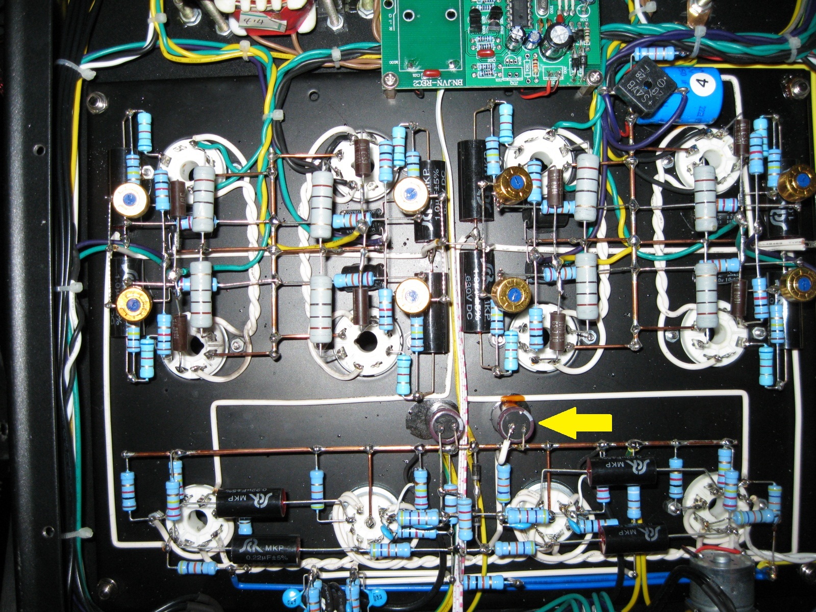
those sure look like cathode caps for the input section, and anything
that is 47uf will work, likely the maximum voltage is on the order of
20 volts, so just about anything would work. Now if a tube shorted
then there would be a lot more voltage on that cap, but i doubt the
front end power supply is more than 250 volts.
Thanks Dr G !
I will take some hi rez shots and post them for you to pour over when you have some time to do so. I really appreciate the help !!! I'm not entirely convinced this 22uf cap is the only fault in this amp but it's the only part that does not check out (so far). I'm hoping the 2 power trannies and the 2 output trannies are still good but I have yet to test them. There are 2 chokes in the main chassis as well as you will see from the larger pic. The topology (my crude interpretation such as it is) is 2 power trannies outboard (separate chassis) connected by a set (A and B channel) of heavy duty multi pin lines, PP using 8 x EL34s, preamp uses 12AT7 x2 and 6SN7 x2. It has the option via toggles on the front panel to run triode mode and as a pure power amp ( I use it in power amp mode with the mode switch set at Ultra linear). I will include shots of the pin that is the source of the blown fuses (each and every time I tried to fire up the amp from the initial attempt after testing another amp that I had just finished repairing the fuses kept blowing before I had even thrown the power switch). The power amp section must have voltage even with the power switch on the main chassis is off. It's an odd arrangement to the usual setup but the main power humpty (MeiXings name for it) is fused at the IEC inlet (4A 5mm x 200mm 250V SB)
It's pin 6 from the A channel umbilical. I checked the cables for shorts as well as the pin sockets on both ends...no shorts in the cables or the jack wiring. The main PSU caps all check out but I have yet to test the diode bridge (if that is the right terminology).
In the meantime I will order the JJ's from PCX (along with other parts for another project) and have those in hand by mid next week (or so).
Pics....
As you can see I had changed out some resistors from the cheap stock 7W 10R's to Mills 10R 12W. I also added 8 x K42 - 0.1uf 630V PIO bypass caps to the MKP 1.0uf 650V stock units. This arrangement has been running like this (up until the fault occurred) for well over a year. When the first fuse blew I swapped out the entire complement of tubes for a known good set (FYI). No change as it blew the second fuse like the first.
"A" jack is the upper right hand position.

Amp side close up of "A" channel umbilical

Power Humpty back panel

Close up of diode bridge

Close up of PSU section

Close up of the rest of the circuit

I hope these are better shots Dr Gilmore. My camera isn't the best that's for sure and I'm no photographer. If you need internal shots of the power humpty just say the word and I will dissemble it and get those up ASAP.
Two additional areas of note are the diodes (some charring by the looks of it) and the power switch. I wonder if that mains switch has given up the ghost ? "A" channel's umbilical seems to coincide with the 6& 7 pins that lead to the L and N tabs of the power switch, although I can't be 100% certain of that. I will test the switch to see if it's working as it should.
Peete.