Torpedo III Build Thread
Sep 20, 2015 at 5:56 PM Thread Starter Post #1 of 322

tomb

Member of the Trade: Beezar.com
Joined
Mar 1, 2006
Posts
10,890
Likes
1,049
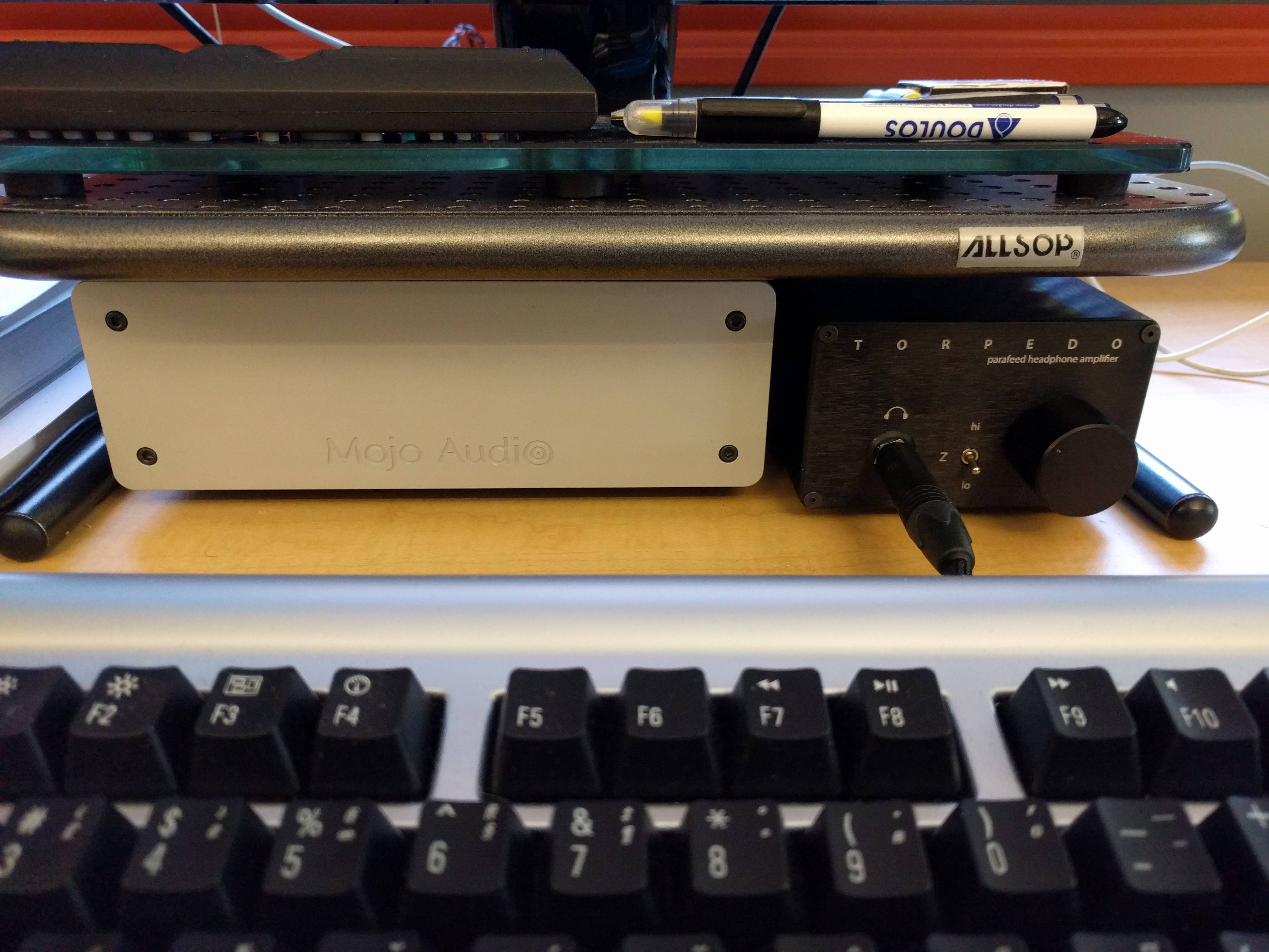
Some of you have built a Torpedo, designed by Dsavitsk of ECP Audio.  The Torpedo has been around for awhile now and represents a true, output-transformer-coupled tube headphone amplifier.  What made the Torpedo unique is that except for a single volume pot ground wire and a PCB safety ground wire, the entire high-voltage, tube-transformer coupled design is contained on a single PCB - no other wiring, no point-to-point construction, and with the supplied enclosure - no casework fabrication.  The combination provided a lot of DIY-ers with the ability to construct a full-function, high-voltage tube/transformer amplifier safely and easily. (I count myself among the ones scared to death to ever try high-voltage construction with point-to-point!)
 
The Torpedo went through some teething pains early on in trying to reduce noise and hum.  However, with the help and patience of many along the way - Dsavitsk, Morgan Jones, Kevin Gilmore, and Jim Cross of vacuumtubesinc.com, several tweaks were discovered that resulted in a noise-free and high performance design. These consisted of 1) the zener diode tweak, 2) the rectifier snubber tweak, and 3) the discovery of the E90CC/5920 tubes.  The result is a noise-free, high-performance tube-transformer (parafeed) amplifier.
 
Meanwhile, Dsavitsk continued to refine the basic planform using tubes, Edcor transformers, and 4 x 14" PCB.  The Torpedo II was created and a couple of prototypes built.  These used 6922 tubes, but resulted in more expense without a significant performance advantage over the Torpedo I, especially compared to a Torpedo I using the E90CC tubes.
 
Back to the drawing board, Dsavitsk decided to use elements of a solid-state, differential circuit in a tube-hybrid arrangement, all tied into output transformers, again in a parafeed arrangement.  This is a singular and - to my knowledge - totally unique amplifier design.  Learning from our previous experience in teething pains with the Torpedo, we built several prototypes ourselves and went through a number of changes before arriving at the DIY kit that you will see here.  We think that many of you will find the cost and effort of assembling this kit well worth your while.
 
I won't go over the construction in excruciating detail as with the Torpedo I.  That build thread is highly documented and building the two amps are very similar.  This is more an effort to note the differences in assembly from the Torpedo I.
 
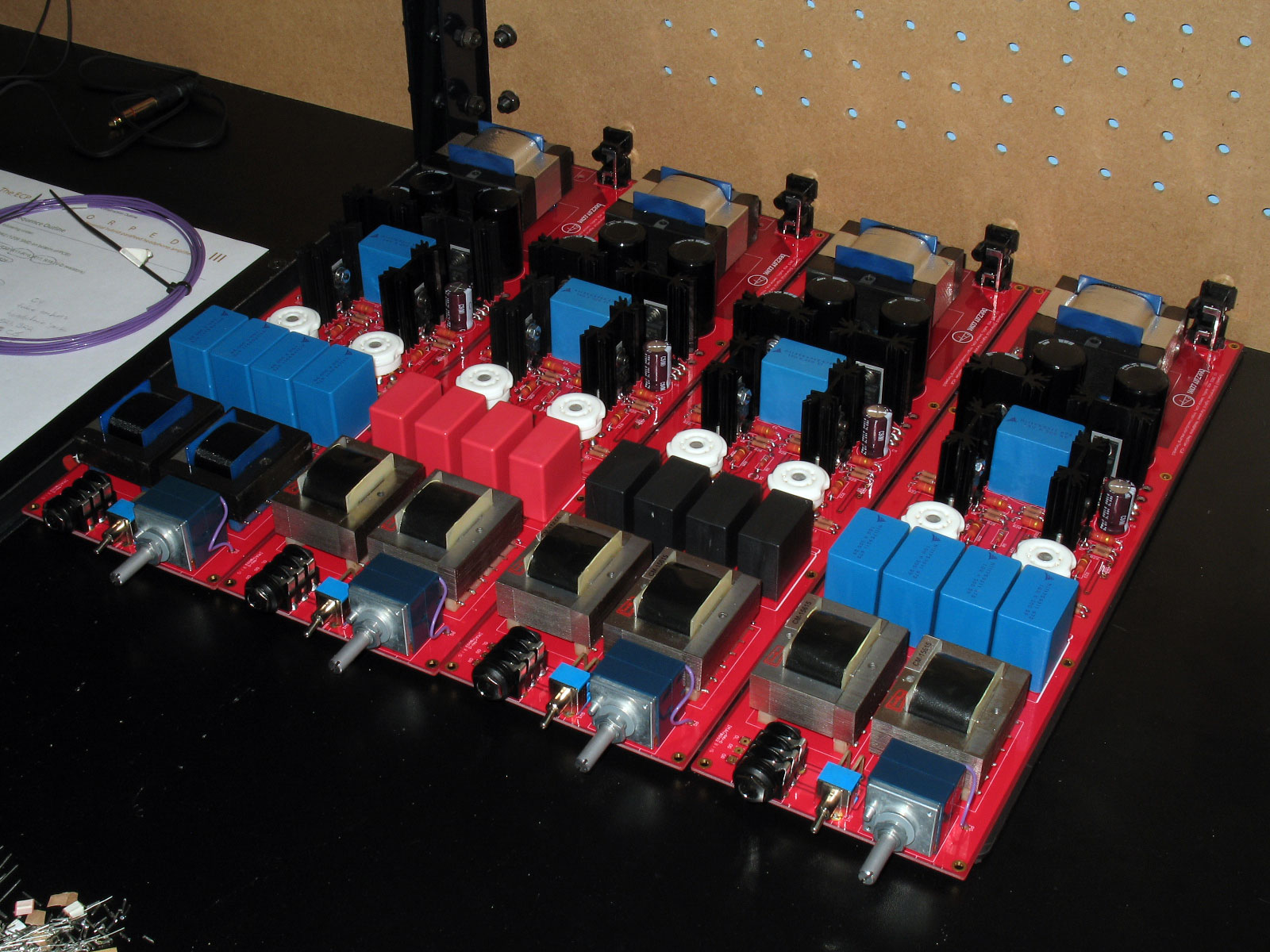
Starting as I always do, you will note the assembly setup below:

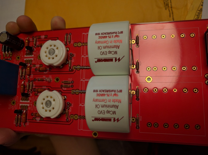
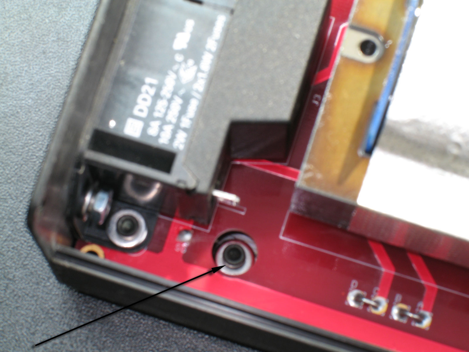
We went with Red PCB and Gold plating/pads this time, all of which is ROHS compliant.  To the right, you can see my trusty Hakko - still going strong after 9 years!  Brass wool, which let me stop using the sponge altogether and it does not reduce the temperature of the iron tip very much, so the work goes much more quickly.  Solder and de-soldering braid is to the left.
 
In the center, the PCB on my piece of high-quality 1 x 10 pine (also 9 years old!).  The first thing you notice is that the PCB is longer than the building board.  That's OK - we only need to access certain portions of the PCB at a time.
 
At the left, my collection of standard tools for assembling a through-hole PCB: scissors for opening the parts packs, cutting part tapes, etc., a lead-bending tool, flush cutters, and smooth-jaw needle-nose pliers.  In addition, for those things that always seem to crop up that can't be handled by all the other tools - a trusty Leatherman multi-tool knife.
 
Solder, as always, is Kester 63/37 rosin core, 0.025" diameter.  This is good for both through-hole and SMD work, too.
 
Besides the window, there is ample task-lighting both in the bench and a task lamp in the upper corner of the building bench.  I simply used a table in the past, but moving a year ago gave me enough room to improve my setup.  It's not needed just for the Torpedo III, though - a table with a lamp will do just fine.
 
EDIT: forgot a zero in that solder diameter. 
wink.gif

 
Sep 20, 2015 at 6:15 PM Post #2 of 322
Standard through-hole construction usually begins by soldering in the lowest-height parts first, following by remaining parts in gradually increasing heights.  This is done with the method I use - the pine board - because I place the part, turn the PCB over and then press down on the PCB and board while soldering.  This ensures the part is soldered flush to the PCB, without purchasing one of those expensive Panavise units.  However, it does mean you need to progress linearly with the height of the parts.  That doesn't mean I don't make a mistake and solder something out of order - as you will see - but it helps.
 
Using that strategy then, the first parts to go in are the small diodes, D1 and D2 -


Next up are the heater rectifier snubbers, just like the final tweak on the Torpedo I.  In the case of the Torpedo III, bridge rectifiers are used, so only two snubbers are needed.  As with the Torpedo I, these are on the bottom of the PCB.  As with any SMD soldering, the first step is to tin one of the pads for each of the snubber caps, as you see in this pic:

 
And as follows with DIY-SMD soldering, melt the solder you just placed on one of the pads and while holding the iron keeping it melted, use your other hand (holding the SMD part with tweezers) to move the SMD cap in position.  Then while continuing to hold the chip in position with the tweezers, remove the soldering iron.  This allows the solder to cool on that one side and the SMD chip is locked in place.  Go back and add solder to the other pad and you've soldered the SMD part!  It's a lot easier than it sounds.  You can re-heat to your heart's content until you get the SMD chip correctly positioned - as long as you don't solder the other pad.  When you're happy with the position, then solder the other side.  Here we are with them soldered:

 
Sep 20, 2015 at 6:44 PM Post #3 of 322
Next up in the part height sequence are the V-D resistors (Vishay-Dale).  The V-D resistors on the Torpedo III are all RN-55 size, so no worries about different sizes.  However - as always - please, please solder the V-D resistors with their ohms value clearly on top.  Unlike traditional resistors, V-D resistors are not color-coded.  If you have to go back and trouble-shoot,  and the ratings of the resistors are not top-oriented, you are at a loss to perform one of the easiest trouble-shooting checks: whether the resistors are mixed up.  Measuring is often not productive, either, because many resistors may be in parallel with something else, complicating any reading you might make with a DMM.
 
There are basically four rows of V-D resistors in various orientations (one all by itself) as shown -


Next are the higher-wattage resistors -

 
Finally, there are a few 2W resistors that are even larger:

There are basically two rows of these resistors and one by itself, for a total of 9.
 
Finally, there are three large diodes:

Be certain to match the orientation of the diodes on the silkscreen.  I must've not been paying attention and soldered two of them in backwards.  De-soldering braid to the rescue!
 
That finishes it for resistors, diodes, and other small parts ... Wait!!  I forgot something, as usual:

Just as with the Torpedo I, the Torpedo III can be configured for either 110V or 220V.  This is accomplished by soldering jumpers at the Power Transformer (PT) position.  The jumper pads are labeled A, B, C, and D:
  • To configure for 110V house voltage, solder two jumpers, one from A to B and one from C to D.
  • To configure for 220V house voltage, solder only one jumper from B to C.
I'm in the United States, so the photo shows the two jumpers that will configure the PT for 110V mains.
 
More later!
 
By the way, you may notice some extra diode positions on the PCB: D7, D8, D9, and D10 are not populated.  The Torpedo III is complete without them.
 
Sep 22, 2015 at 9:36 PM Post #4 of 322
Back to it!
 
Next are the TO-92 parts:

Note the two by the tube sockets.  These are actually integrated circuit regulators.  DO NOT SOLDER THEM COMPLETELY FLUSH TO THE PCB.  We'll show why later when we solder in the tube sockets.  Again, if you are using my pine board method, you should be able to insert all of the TO-92 devices, flip the PCB over and have the TO-92 devices support the PCB upside down while you solder the joints.
 
The smallest electrolytic capacitor goes in next.  The ones supplied with the kit and on the BOM have the type of leads with the "kink" or "knee-bend" in them.  So, don't worry about trying to get the cap flush to the PCB.  Just make certain the cap is securely soldered and is stable.


Next up in height are the tube sockets and the Z-switch.  All three are about the same height:

As in mentioned in many of my build threads and on the website, remember that the tube sockets are just as much a mechanical/structural connection as they are electrical connections.  So, ensure that the joints on the pins are good and sufficiently soldered.  While soldering from the bottom of the PCB, the solder should be sufficient to wick all the way to the other side and some length up the pin legs.  That said, please refer to the very next pic and description below before soldering the tube sockets into place.
 
NOTE: Notice that those are 9-pin sockets!
 
Similarly, the joints on the Z-switch must be sufficient and secure.  However - in the case of the Z-switch - the body and much of the inside is plastic, so wait between soldering each joint and allow it cool.  Otherwise, you could end up with a plastic puddle on the PCB instead of a nicely installed switch.
 
As mentioned, here is the reason we do not want to solder the TO-92 regulators (IC1 and IC2) in front of the tube sockets flush to the PCB:

The real estate on the Torpedo III PCB is very limited.  In this case, IC1 & IC2 were moved forward as far as possible with endangering the traces beneath by having them too close to the output transformer traces.  Even so, they must be bent forward slightly to make room for the tube sockets.  You should be able to bend them far enough forward that no part is touching the tube sockets.  Don't solder the sockets in until you are assured that the regulators are not touching.
 
Sep 22, 2015 at 9:48 PM Post #5 of 322
Next up are the bridge rectifiers, BR1 and BR2:

These are easy enough to insert, but beware - they are very large and the leads are very big.  It may take some extra heat to get them soldered.  Also, it's best to solder one lead on each (while the PCB is upside down), then flip over the PCB and make certain that they perpendicular to the PCB.  The leads are so big and tough that when you get all four soldered on each bridge rectifier, it will be impossible to bend them back so that the rectifiers are straight up and down.  The goal is that you do not want them touching the power transformer.
 
Shoot!  Another one I forgot - the LED:

That's OK - it's pretty easy to install.  I think the "+" sign didn't make it through it our quality check.  However, the long lead goes next to the resistor. Install the LED at the height you desire.
 
Next is the headphone jack:

As with the tube sockets and the switch, there is a mechanical connection with the solder joints, but the bulk of the headphone jack is plastic.  So try to get solder wicking up the pins on the top side of the PCB, but give it time to cool between joints, otherwise the plastic will melt.  Do your best to get the headphone jack flush with the PCB, parallel to the PCB surface in the horizontal direction and perpendicular to the front edge of the PCB.
 
Sep 22, 2015 at 10:05 PM Post #6 of 322
The ALPS Blue Velvet volume pot is next:

As with the headphone jack, remember there's a lot of plastic there, so go slow on soldering the six pins and try to allow sufficient cooling between joints.  Also as with the headphone jack, do your best to have the pot shaft parallel to the top surface of the PCB and perpendicular to the front edge of the PCB.  This will make aligning the volume knob much easier when you case it up.
 
I soldered the output transformers in next:

As with everything else, try to keep these flush to the PCB and oriented orthogonally. Rotate soldering the pins in a sequence to keep things cool.  The PCB pin runners on the transformers are plastic and they will melt.  Solder a pin on one transformer and then solder the same pin on the other.  Go back to the first transformer to solder the next pin, then switch to the other transformer.  Do this taking turns from one transformer to the other and you should be able to keep things cool.
 
So ... what do I always forget before this step?
 
The dadgum ground wire for the pot!

It seems I do this every time I build a Torpedo: forgetting to install the ground wire before soldering in the output transformers.  Luckily, I have a very small screwdriver that I can use, so I can get the pot screw tightened securely down on the ground wire, even though the OT is in the way.  You can probably see a little scrape mark on the laminations in line with the pot screw. 
frown.gif

 
Another view:

It may take some effort, but be certain the screw engages the front panel of the pot and that you have some ability to make it tight.  In my case, I always use 22ga SPC teflon hookup wire (Navshipps/John's Wire Shop on ebay).  It's pretty thick compared to the screw, though, but with some effort you can get the wire compressed under the screw and actually have it threaded into the pot's front panel.
 
Needless to say, this is an awful lot easier if you do it before soldering in the OT's. 
wink.gif

 
Sep 23, 2015 at 8:50 PM Post #7 of 322
Moving right along, we installed C5:

 
C3:

 
Next up was C6.  It has a silkscreen for either a large film box cap (as shown here) or an electrolytic.  I asked Dsavitsk which to use and he said the film cap sounds better.  Good enough for me. 
wink.gif


Yes - besides C6, I'm sure you've noticed all of those big box film caps - five of them, counting C6.  To explain some of this, it might be appropriate to show Dsavitsk's schematic of what's going on:

 
This is what makes this amplifier design unique.  I'm not aware of another amp such as this.  Basically, the tube intputs have been split into their constituent differential signals.  Or, put another way, the outputs from the tubes are balanced leading into the output transformers.  The OT's are still coupled in a parafeed arrangement, but they are accepting balanced/differential signals.  Differential signals mean four signal lines to the output of the amp, or two per output transformer, thus four capacitors to AC-couple the signals to the transformers.
 
In the case of the Torpedo III, Dsavitsk arrived at 10uf for the parafeed capacitors.  Needless to say, that's pretty big.  The Epcos capacitors shown here are what will be supplied in the kit.  They have a great reputation for sound quality at an inexpensive price.  So, C7, C8, C9, and C10 were installed:

 
Next up are the heat-sink mounted solid-state devices.  Because of the differential part of the circuit, there are two output transistors for each channel (as shown in the circuit schematic above).

Note the two heat sinks on the right.  They have transistors mounted on both sides to handle the four signals coming from the two tubes.
 
Solder all of these into place on the PCB (refer to the silkscreen labels and the BOM for the correct parts):

 
Sep 24, 2015 at 9:38 PM Post #9 of 322
The RCA jack comes next - be sure you push the tabs all the way into the holes.

 
The only capacitors left to install are the two large power caps, C1 and C2:

 
Next up is the Power Transformer (PT).  It might have been the IEC inlet, but I'll explain that below:

As with the OT's, try to get the PT flush and alternate soldering pins from one side to the other, so that you don't melt the plastic rails.  When you turn the PCB upside down, try to stabilize the rest of the PCB.  At this point, the PCB is a very long lever arm with big weights on both ends.  The PCB will definitely flex, or worse - if you let it.
 
The IEC inlet is actually shorter than the PT.  However, after putting together a lot of these, Dsavitsk suggested the best method for installing the IEC inlet and the back plate. The best method requires you to go ahead and mount the IEC inlet to the backplate, first, then mount it to the PCB and solder the IEC pins in place.  The reason this is done is because there a wide tolerance is needed with the back plate fit up with the case.  The reason is with this sort of length of PCB and case (14"), the variances in tolerance - if you solder the IEC inlet to the PCB first - may very well result in your not being able to get the back plate flush with the back of the case.
 
So, mounting the IEC inlet to the back plate first - solves this problem.  For somewhat similar reasons, the tolerance fit of the IEC inlet and the large rectangular opening is quite small.  Your initial attempts to get the IEC inlet protrusion fit through the rectangular opening may fail.  The tight fit is there for a purpose - safety first.  I have seen a builder take serious unapproved shortcuts and simply press fit the IEC inlet to the back plate without any mounting hardware at all. DO NOT DO THIS - IT IS NOT SAFE.  Instead, work carefully to press fit the IEC into the back plate opening.  When you get all four corners through the opening, then use the mounting hardware to get the IEC inlet flush.  Otherwise, you may bend the back plate.  Usually, all it takes is a small file to round off the corners and the inlet will fit.
 
The recommended hardware is two sets of 4-40 x 3/8" socket head cap screws with washers on both sides, and lock washer plus nut on the inside.  Obviously, if you are at all interested in looks, please use the black washers on the outside (supplied in the kit).
 
Here we have the back plate with the IEC inlet mounted in place.  The arrows indicate where you should file if the fit is too difficult:

 
And a view from the inside:

As noted, the arrows indicate where the flat washer, lock washer, and nuts are to go.  Please do not neglect this hardware and ensure that everything is flush, snug, and tight before proceeding further.  This is where the mains voltage comes in and ensuring that this is assembled and installed properly is for your own safety.
 
Sep 24, 2015 at 9:56 PM Post #10 of 322
When attaching the back plate assembly to the PCB, line up the IEC inlet pins with the pads on the PCB and line up the RCA jacks with the holes in the back plate.  The RCA jacks have plastic circular bosses that protrude from the RCA jack assembly, ahead of the actual metal jacks themselves.  The holes in the back plate are sized for these bosses, but you must make certain that they line up and that the bosses are poking through the holes.  As it is, there is enough variance that the back plate will actually stick out a bit further from the PCB on the RCA jack side, but it's not enough to affect the final assembly from being flush.

Use the same hardware mounting that you used on the back plate, except black finish washers are not needed on the inside.  The silver ones are fine. 
wink.gif
  So, socket head cap screw with washer on top of the IEC mounting tab, then washer, lock washer, and nut on the bottom of the PCB.  Do this in two places.
 
Mounting hardware on the other side in this view:

 
Once you do this and everything is bolted up tight, then and only then - solder the pins of the IEC inlet on the bottom of the PCB.
 
You might have noticed in the last couple of pics that I had already soldered the safety ground in place, but here's a look on the back side, along with the IEC inlet pins all soldered up nicely:

The arrows represent the IEC pins that need to be soldered.
 
Meanwhile, you can also see the safety ground.  I like to use some extra length so that I can bend it easily.  That makes it easier for me to line up the lug with the hole in the PCB and the mounting hole in the bottom of the case.  If you figure out a better method, use it and then let me know about it. 
wink.gif
  I also both crimp the lug and put some solder in there between the hookup wire end and the metal part of the lug.
 
In this view, you can see the safety ground, IEC pins, and most importantly - the back plate's position relative to the back edge of the PCB.  As noted previously, you can see that the RCA jack side of the back plate sticks out a bit further than the other side.  Make sure the RCA jack bosses are sticking through the back plate holes.  Even so, there will be the difference in clearance shown here, even with the jacks as flush as you can make them.  Not to worry, though, everything will fit up tight and flush with the case. 

 
Sep 24, 2015 at 9:59 PM Post #11 of 322
The PCB is now complete and ready for assembly into the case!

 
I would continue, but I need to take some more pics.  I got so excited at this point, that I assembled the whole thing and started using it without taking more photos. 
biggrin.gif

 
Sep 25, 2015 at 4:31 PM Post #12 of 322
Slide the PCB into the rear of the case (remember the back plate is still attached to the back of the PCB) using the 2nd slot from the bottom.  You should have the two standoffs attached to the PCB at this point.  The standoffs (4-40 x 5/16" tall) should include a single #4 flat washer between the standoff and the bottom of the PCB to get the spacing exactly correct.  Attach on the top of the PCB with a 4-40 x 3/8" long socket head cap screw, a lock washer, and a flat washer against the top surface of the PCB.  The lock washer on the top side (a bit counter-intuitive from conventional practice) ensures that the screw stays locked when you attempt to remove the screws from the bottom of the case that go into the other side of the standoff.

As noted above, there are two spots available for the standoffs.  The Torpedo I uses three, but we were being especially cautious on that design.  Regardless, one of the standoffs in the Torpedo III goes right between the tubes, which is where the PCB experiences the most stress (from plugging and un-plugging the tubes).  This has worked out fine for the Torpedo III and with three prototypes in the books so far, there are no problems with support.
 
Here's a look at the bottom of the case -

Use a 4-40 x 1/4" long socket head cap screw with a single flat washer to screw into the standoffs from the outside.  You probably won't be able to get the screws screwed in all the way flush to the bottom of the case - there simply isn't enough room for threads in the standoffs.  However, the washer + standoff is completely flush with the PCB and the inside of the case so there is no up and down movement.  Overall, the PCB is completely locked from any up and down or sideways movement.  If it worries you that the bottom screws are not completely flush, use another flat washer under the screws on the bottom of the case.  I think that leaves precious little threads in the standoffs to really grip the screws, but I've done it both ways in the past.  There will be plenty of washers included in the kit.
 
Also note that with a case this long, it just seems a bit better to use bumpers in the middle, besides on both ends.
 
You can see the third standoff position is simply an open hole with the Torpedo III.  It is, after all, the very same case used for the Torpedo I.
 
Finally, note the safety ground nut at the rear.  More on that, next -
 
Here's a view of the safety ground screw underneath the PCB:

NOTE: before assembling the PCB, use a knife or file to scrape away the anodizing on the INSIDE of the case around the safety ground hole!
Aluminum anodizing has insulating qualities and you will not get a good safety ground connection if you don't do this!
 
When assembling, I push the PCB in until I reach the safety ground opening in the PCB that you see here.  Then I check to make sure the safety ground wire and lug assembly is clearing the case and that the lug is lined up with the hole.  Then I push the PCB in the remaining length.  There is usually enough friction on the end of an socket-head ball-driver to hold the cap screw and two flat washers (for spacing) sideways.  So, with the Torpedo III resting sideways on the side of the case, I insert the cap screw/washer collection through the PCB hole and through the hole in the lug underneath.  Before you do all of this, use the socket-head ball-driver to line the lug up with the mounting hole on the bottom of the case, if you can.  Then while the wire/lug is suspended in position, use the ball-driver to push the screw/washer collection through the PCB hole, through the lug, and through the hole in the bottom of the case.
 
If you mess up, just pull the PCB back out a bit and shake the screw and washers out.  Push the PCB back into the case, line up the lug with the holes, and try again.
 
Once you get everything pushed through to the bottom of the case, then apply another flat washer against the case, a lock washer and a nut.  Tighten everything up and continue assembling the rest of the case.  Here's a closeup of the safety ground nut and washers on the bottom of the case:

Note the proximity of the height of the washers/nut assembly to the height of the bumper.  This is close.  It's why I said use two washers under the socket head of the cap screw on the inside.  A 1/4" socket head screw is simply too short to manage poking through those holes, but a 3/8" screw is going to stick out from the bottom of the case further than the bumpers.  This would not be good for your furniture!  So, be sure to use two washers under the screw head before poking the screw through the lug and holes from the topside.
 
The next step is to screw the 1/4" socket-head cap screws with washers into the two standoffs!
 
Sep 25, 2015 at 4:59 PM Post #13 of 322
Assembling the rest of the case is pretty easy.  Besides a 4-40-sized socket head ball-driver (or allen wrench), you need the following shown below -

I've already cheated and attached the front plate and back plate on the bottom.  However, you see the tools in this pic that you can use.  No, you don't really need them, but they will help you from scratching up the case.  Both the Alps volume pot and the Neutrik headphone jack use 7/16" diameter nuts.  A small closed-end 7/16" wrench is a great tool and won't scratch things up.  Remember that you're dealing with plastic, here, so don't go torquing the heck out of those nuts!  They only need to be snug!
 
The other great tool, especially for the counter-sunk 4-40 socket head screws is the Bondhus 1/16" ball driver.  This tool is so convenient for removing the screws of the top case lid that I provide one with every Torpedo kit sold!  NOTE: You need to remove the case lid to change out the tubes, so this might be done quite a bit and the Bondhus driver is really handy!
 
Finally, a precision screwdriver is used for the volume knob.  This varies, though.  I purchase the 30mm aluminum knobs from PartsPipe/hongkongsuperseller on ebay.  They seem to have the best, large knobs that don't break a wallet, but consistency is sometimes pretty bad.  I've gotten them with flat-head set screws, allen set screws, and once even got a bunch with two set screws.  Use the tool you find most convenient.  With a flat head screwdriver, though, you need to be certain the blade is not wider than the hole where the set screw is inserted.
wink.gif

 
Here's a pic using the wrench on the volume pot nut.  You should attach the front plate to the pot and headphone jack, first.  Get the nuts snug, but not overly tight, then screw in the front plate screws to the case extrusion.  Dsavitsk mentioned that he does the front plate in a similar manner as the back plate.  In other words, he attaches the headphone jack and the volume pot to the front plate, then solders them into the PCB.  That's one way to make certain you get the headphone jack and pot straight, so you might try that if you're interested.

The headphone jack comes with three spacers, a tapered spacer and the ferrule nut.  I use a single spacer on the inside, then one spacer, the tapered spacer, and the ferrule nut.  I just think that looks best, but you might like another spacer in front or only the tapered spacer - it's up to you.
 
 
There's no pic for this (and I cheated again by already doing it), but you need to cut about 1/4" off of the ALPS shaft to get the knob flush.  I do this with a Dremel cut-off wheel, after I package up the case in a small plastic garbage bag.  I poke a hole in the bottom so the pot shaft can poke through, then I tape all around the shaft and the garbage bag at the hole.  This makes certain that no aluminum dust gets into your Torpedo and makes a fuss with that high voltage! 
wink.gif
  You may have a different method.  The Dremel cut-off wheel is a hassle sometimes.  The top and bottom surface of the wheels will get loaded up with aluminum, which makes them catch in the cutting throat of the pot shaft and then snap!  The wheel will break.  Some people have mentioned a hack saw before, but I just think that puts a lot more stress on the pot and its internals.  Whichever method you use, go slowly and be sure to protect the rest of the amp from the aluminum dust that results.
 
When you're ready to mount the volume knob, use a credit card or similar to wedge in under the back of the volume knob.  This will give you the closest spacing without having the knob bind against the front plate.
 
Here is the amp with both end plates screwed in at the bottom:

I haven't mentioned this much, because it has little to do with actually building the amp, but note the tubes.  The Torpedo III can use just about every 12A*7 tube made - 12AU7, 12AT7, 12AY7, 12AX7, etc., and all their variants.  I ran the second prototype with 5963's, in fact, and it sounded GREAT.  However, Dsavitsk's design is really optimized on the 12AY7 for the best all-around gain.  So, two modern, new manufacture Electro Harmonix 12AY7's will be supplied in all of the kits.  The rest of the tube rolling will be left up to you. 
wink.gif

 
Here's a pic of the back plate, since we've seen so much of the front plate.  Yes, I've already attached the lid in this pic.  Regardless, note the socket head screws, black washers, and the IEC inlet with the rectangular section poking out properly.  Oh!  I forgot to mention to screw a 4-40 socket head cap screw + black flat washer into the RCA jack assembly.  This is the screw/washer you see below between the IEC inlet and the RCA jacks themselves.  The plastic is so soft for the RCA jack assembly, that even the 4-40 screw self-threads itself when you screw it in.  Again, this is plastic you're dealing with, so get the screw/washer snug and flush, but don't go torquing crazy!

 
Finally, a couple of shots of the completely assembled amplifier - Front:

 
and Back -

 
DONE! 
biggrin.gif
 
 
Sep 25, 2015 at 5:13 PM Post #14 of 322
So, how does it sound?  I will try to run tests this weekend and compare them against the Torpedo I.  Until then, the best way I can state it is:
  1. First, no hum, no noise whatsoever (just confirming this one).
  2. Second, pretty much all the personality of the Torpedo I, but more refined.
  3. Third, about 20% better high-end response, with all the rest being similar to the Torpedo I: bass and midrange.
  4. Lastly, a cleanness of sound that is amazingly non-fatiguing over extended periods of listening.  This can't be over-emphasized.  Detail is extended, yet without tizziness or harshness.  Anyone who ever had an opportunity to listen to ECP Audio's DSHA-1 knows what I'm talking about.  For the rest of you, you are in for a treat.  The amp does nothing spectacularly, so it may not amaze at first listening.  It just keeps on going with a freshness and lack of fatigue that's quite amazing.
 
How does it sound with Cinemag nickel-core transformers instead of Edcor steel?  Dsavitsk put the Cinemag prototypes on the second prototype Torpedo III we built and has had some very (very!) surprising comments.  I haven't had the opportunity, yet - but will let you know when I do.
biggrin.gif

 
That's it for me - the support website is next and then they should be available.  Enjoy!  
 

Users who are viewing this thread

Back
Top