The Zishan dsd's corner
Dec 16, 2020 at 6:13 AM Post #3,241 of 3,711
@londere yes I try 3 different chargers with 3 different mini USB cables and everyone works with Topping NX3s for example no one works with ADIII.


That was a big drop of Tin mearging all 3-4 legs elements together. Removed this but maybe inaccueate because still nothing happen.
Device according specification would work on the cable and charge even same time. Diode nierby USB port of charging not glow and device not charge like no connection with min USB port.
My bad @Setmagic, I meant to use an external battery charger such as this charger, also on my GAD Dual ak4497 I need to reflow all the SMD components due to problems of cold junction of the PCB and the components in my case the LPF resistors and capacitors. By your pictures, the USB looks with the problem stated, the bad cold junction of the solder paste. Also check the IC with a multimeter, as I can see the charging stage is based on TC4056A and TPC8107
 
Last edited:
Dec 17, 2020 at 2:31 PM Post #3,242 of 3,711
Progress so far. Still haven’t had a chance to listen to it as I’m waiting for the panel mount audio jacks. I’m using an OPA1688 as the headphone driver.
 

Attachments

  • 5C906764-A3E6-416C-8563-F440E0296330.jpeg
    5C906764-A3E6-416C-8563-F440E0296330.jpeg
    4.6 MB · Views: 0
Dec 17, 2020 at 3:44 PM Post #3,243 of 3,711
@londere thank You for professional review. Sadly everything I must do via electronic service. I don't have skills to replace mini USB or SO8. I can recable and replace big caps.
What about this 3 caps in ADIII can I remove this to make better circuit quality as in DSDs?
 
Dec 18, 2020 at 4:41 PM Post #3,248 of 3,711
I thought of something but I'm not sure how well it will work. Instead of using 100uF caps on the High Pass Filter right after the DAC, I could use 0.1uF film caps and replace the 10K resistor with maybe a 2M resistor to get as far below 20Hz as possible. I am not sure if this makes a difference in the way the hpf works. Any input would be appreciated.
 
Dec 18, 2020 at 11:38 PM Post #3,249 of 3,711
@moshe tes
Sometimes understanding more about a subject requires learning more base knowledge (that we lack).
It's like asking about advance math without knowing how to sum.

The selected R and C will determine the filter impedance.
https://electronics.stackexchange.c...lues-when-designing-a-low-high-pass-rc-filter
It looks like one of the problems would be impedance matching.
https://en.wikipedia.org/wiki/Impedance_matching

In the datasheet they use 100uF 10k, but in the evaluation board they use 10uF 20K, so those values should be ok.
 
Dec 19, 2020 at 9:33 AM Post #3,250 of 3,711
I thought of something but I'm not sure how well it will work. Instead of using 100uF caps on the High Pass Filter right after the DAC, I could use 0.1uF film caps and replace the 10K resistor with maybe a 2M resistor to get as far below 20Hz as possible. I am not sure if this makes a difference in the way the hpf works. Any input would be appreciated.


1. Shunting the main tanks makes sense in systems
nutrition.
If you want to use better quality decoupling capacitors, you can use either very high quality ceramics
with maximum linearity, or WIMA 1uF 63V film, but MANDATORY
with the recalculation of the entire LPF scheme for this denomination.
What you did is wrong! The sound will be too bright!

2. OPA1688 cannot be used in the subtractor stage and simultaneously as a headphone buffer.
You did it wrong!
For correct operation, a faster amplifier is needed in the subtractor,
then, with decoupling, install the AD8397 repeater, or with a maximum ku = 1.3. Then the amplifier will work without distortion for a low-impedance load.

3. Replacing the inductors in the power supply makes sense only when
you are sure that you put the inductors with the best quality factor.
Are you sure you have delivered better inductors?

4. Capacitors in the power supply are also selected with certain characteristics, I'm not sure what you supplied.
 
Last edited:
Dec 19, 2020 at 10:43 AM Post #3,252 of 3,711
I made a small compilation:
DSDs Dual AK4497 OP275 + Muses 8820
DSDs ~ + ADIII Tube 6021 + Muses 8820

DSDs have removed caps from 3,5mm PO.
Recorded via RAW line-in by Zoom H2n to 16bit flac from 16bits flac.
Files was normalized to -0,2.

LINK:
https://drive.google.com/file/d/1ZYKRailIPdRcoEiu2iQGKBbxdospPP3p/view?usp=drivesdk

What's is yours impressions? Can you type which part of track have added Tube preamplificarion? :)
 
Last edited:
Dec 19, 2020 at 6:27 PM Post #3,254 of 3,711
@moshe tes
Sometimes understanding more about a subject requires learning more base knowledge (that we lack).
It's like asking about advance math without knowing how to sum.

The selected R and C will determine the filter impedance.
https://electronics.stackexchange.c...lues-when-designing-a-low-high-pass-rc-filter
It looks like one of the problems would be impedance matching.
https://en.wikipedia.org/wiki/Impedance_matching

In the datasheet they use 100uF 10k, but in the evaluation board they use 10uF 20K, so those values should be ok.

I thought about the impedance, but just ignored it thinking that the LPF op-amp ideally should have infinite impedance anyway. Of course assuming that basic concept applies to op-amps for all applications.
 
Dec 19, 2020 at 6:45 PM Post #3,255 of 3,711
1. Shunting the main tanks makes sense in systems
nutrition.
If you want to use better quality decoupling capacitors, you can use either very high quality ceramics
with maximum linearity, or WIMA 1uF 63V film, but MANDATORY
with the recalculation of the entire LPF scheme for this denomination.
What you did is wrong! The sound will be too bright!

2. OPA1688 cannot be used in the subtractor stage and simultaneously as a headphone buffer.
You did it wrong!
For correct operation, a faster amplifier is needed in the subtractor,
then, with decoupling, install the AD8397 repeater, or with a maximum ku = 1.3. Then the amplifier will work without distortion for a low-impedance load.

3. Replacing the inductors in the power supply makes sense only when
you are sure that you put the inductors with the best quality factor.
Are you sure you have delivered better inductors?

4. Capacitors in the power supply are also selected with certain characteristics, I'm not sure what you supplied.

Excuse the long post, but I will be quoting your statements so as not to cause confusing. I really appreciate your comments, they are very educational. I know it can be frustrating answering noob questions.

"1. Shunting the main tanks makes sense in systems nutrition."

- I am not sure I understand this statement.

"If you want to use better quality decoupling capacitors, you can use either very high quality ceramics
with maximum linearity, or WIMA 1uF 63V film, but MANDATORY
with the recalculation of the entire LPF scheme for this denomination.
What you did is wrong! The sound will be too bright!"

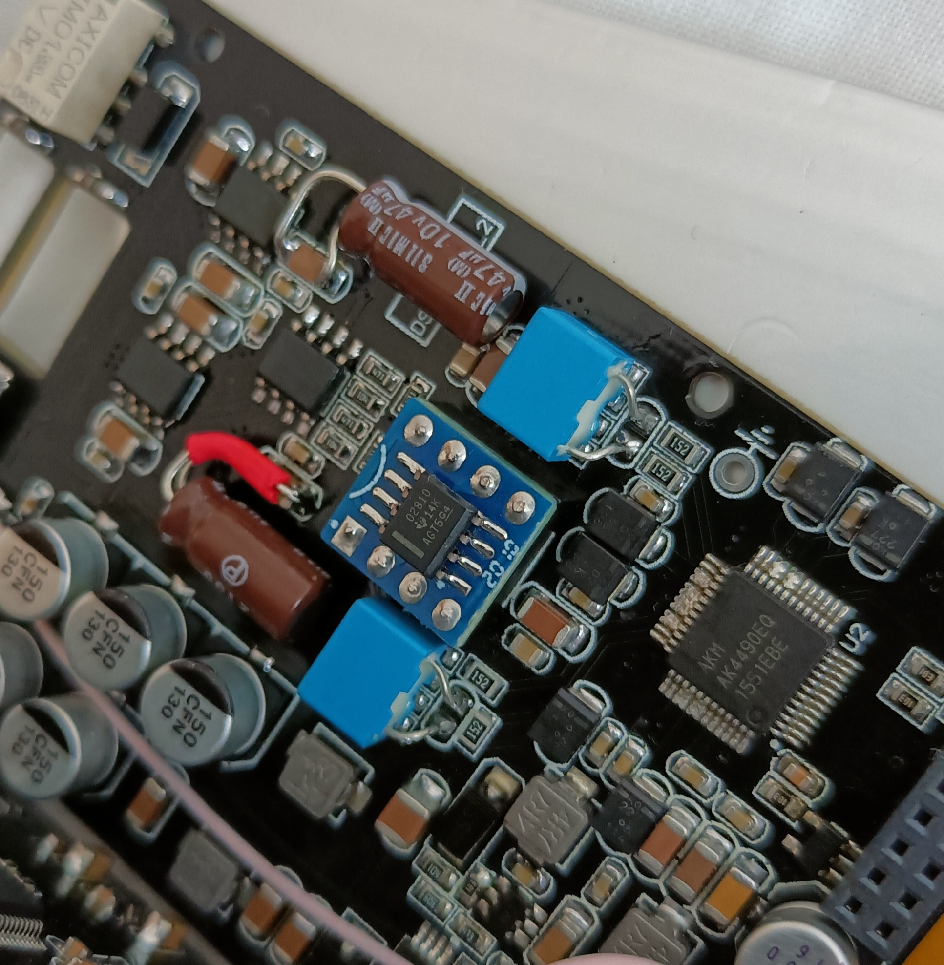
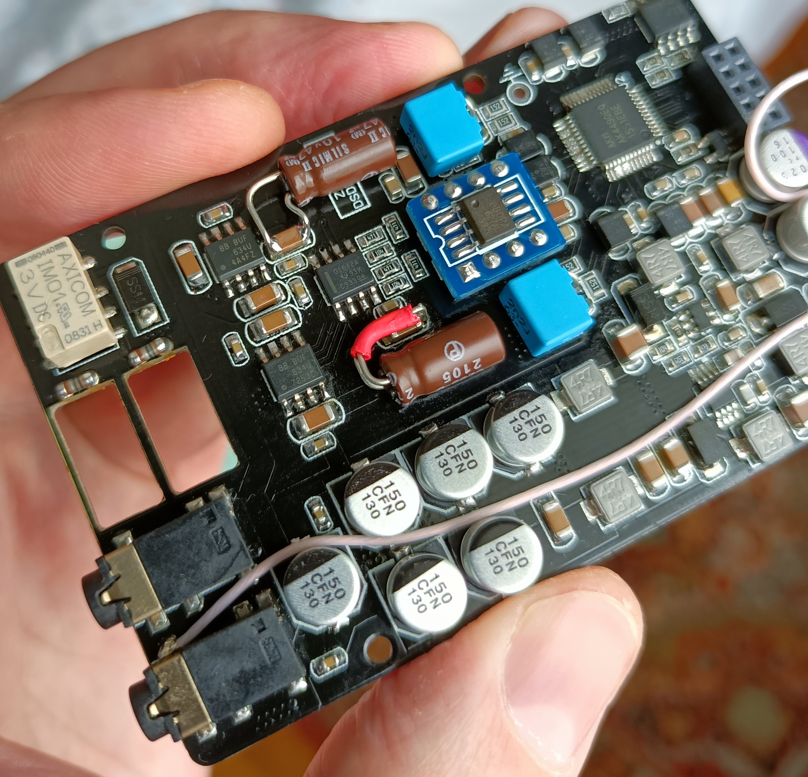
- Which decoupling capacitors are you referring to? Originally, I was talking about the 100uF coupling caps on the hpf located right after the DAC.

"2. OPA1688 cannot be used in the subtractor stage and simultaneously as a headphone buffer.
You did it wrong!
For correct operation, a faster amplifier is needed in the subtractor,
then, with decoupling, install the AD8397 repeater, or with a maximum ku = 1.3. Then the amplifier will work without distortion for a low-impedance load."

- Okay this is good information! Thank you! I used the OPA1688 because I saw someone here who used OPA1622 as both subtractor and buffer and since the difference between the OPA1622 and OPA1688 is not that much, I thought I could do the same. My question is, how about using OPA1612 for subtractor and OPA1622/1688 as buffer? I happen to like how the TI op amps sound.

"3. Replacing the inductors in the power supply makes sense only when
you are sure that you put the inductors with the best quality factor.
Are you sure you have delivered better inductors?"

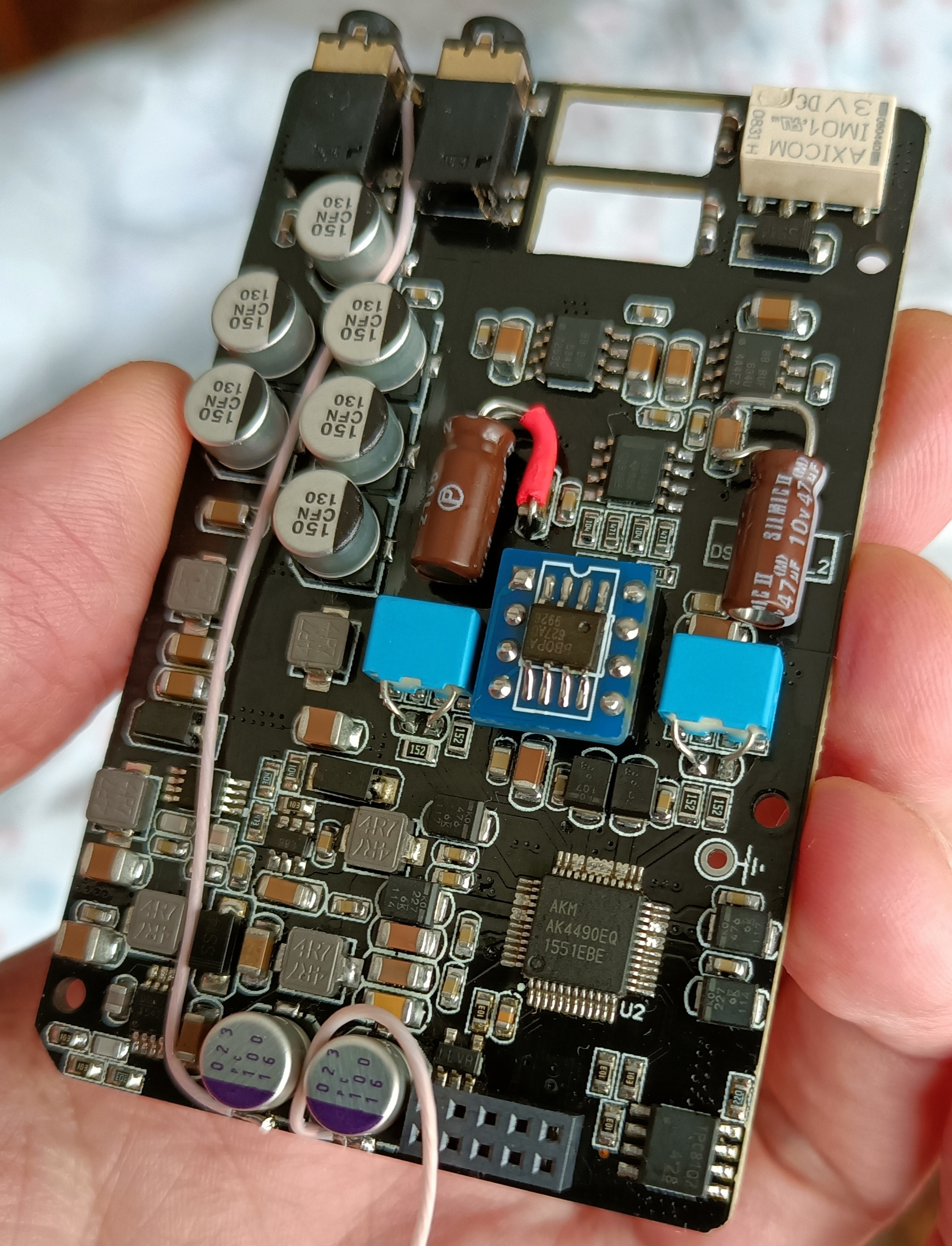
- The only factor I considered is the DC resistance of the inductor. Other than that, the amperage rating. The one I used has a rating of 1.9A and about half the DC resistance of the one that was in the Zishan originally. I assume it is better overall. Here is a link: https://www.mouser.com/ProductDetail/Bourns/SRR3818A-4R7Y?qs=EU6FO9ffTwfji0kq1pAYtg==

"4. Capacitors in the power supply are also selected with certain characteristics, I'm not sure what you supplied."

- I used Panasonic ultra-low ESR caps. They are the FR series.
 
Last edited:

Users who are viewing this thread

Back
Top